
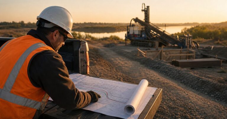
A crossing succeeds when an HDD feasibility study (horizontal directional drilling feasibility study) fixes one achievable geometry, proves the product pipe survives installation, and matches the drilling fluid plan to the ground actually present. This guide sets out what the study must decide, the data set it needs, the four design pillars, the success criteria to fix before design, and a screening go or no-go table. Every figure quoted here is a planning input and must be confirmed by calculation for the crossing.
What Does an HDD Feasibility Study Have to Decide?
A properly scoped study answers four questions: drillability in the ground present, geometry that can be built, risk that can be priced, and a commercial case that stands. A study that leaves any of them open is a drawing review, not a feasibility assessment.
- Is the crossing drillable in the ground actually present, at the required length and diameter?
- Is the geometry achievable, meaning can cover, bend radius and entry and exit angles be satisfied together?
- Is the risk acceptable once the HDD risk assessment has priced the credible failure modes?
- Is HDD the right commercial choice on this crossing compared with open cut, microtunneling or Direct Pipe?
The four feasibility answers are conclusions supported by survey, geotechnical data and calculation, not opinions.
The Data Set an HDD Feasibility Study Needs
Feasibility is bounded by its inputs, and an HDD site investigation that stops at one borehole supports very few conclusions.
The table below sets out the data set a feasibility study needs, why each input changes the design, and the evidence an owner should demand for it.
| Input | Why it matters to the design | Provided by | Evidence to demand |
|---|---|---|---|
| Crossing survey and profile | Cover, curvature and geometry cannot be fitted without it | Owner or surveyor | Signed plan and profile with stated datum |
| Geotechnical investigation | Drillability, fluid loss, reaming behaviour, settlement risk | Owner’s geotechnical consultant | Borehole logs, characterisation profile, laboratory results |
| Utility records and potholing | The bore must clear live services by a defensible separation | Utility owners and one-call records | Marked-up records plus verified potholes |
| Product pipe data | Sets allowable curvature, buoyancy and pull load | Pipeline designer | Pipe data sheet, welding and coating specification |
| Operating envelope | Governs in-service checks and acceptable installation stress | Pipeline designer | Basis of design and line list |
| Site, access and staging | Determines rig class, pit size and pipe string length | Owner and constructor | Site layout and access study |
| Permits and crossing authority rules | Drives cover, casing, monitoring and restoration duties | Regulator and asset owner | Permit conditions and landowner agreements |
Which Two Inputs Decide Most of the Study?
Two inputs decide most of an HDD feasibility study: the geotechnical characterisation profile sets what the bore can pass through, and the surveyed plan and profile set what geometry is available between the entry and exit working areas. In our design reviews, a thin HDD site investigation is the most common reason a feasibility review has to be reopened, as covered in the bore plan and HDD limitations guides in this series.
The Four Design Pillars of a Crossing
Horizontal directional drilling design for a crossing sits on four pillars: bore geometry, product pipe stress, drilling fluid and inadvertent return, and constructability. They interact, and a change to one usually forces a change to another. Published references such as the NASTT HDD Good Practices Guidelines and ASTM F1962 are frameworks to apply, not answers to copy.
Pillar 1: Bore geometry
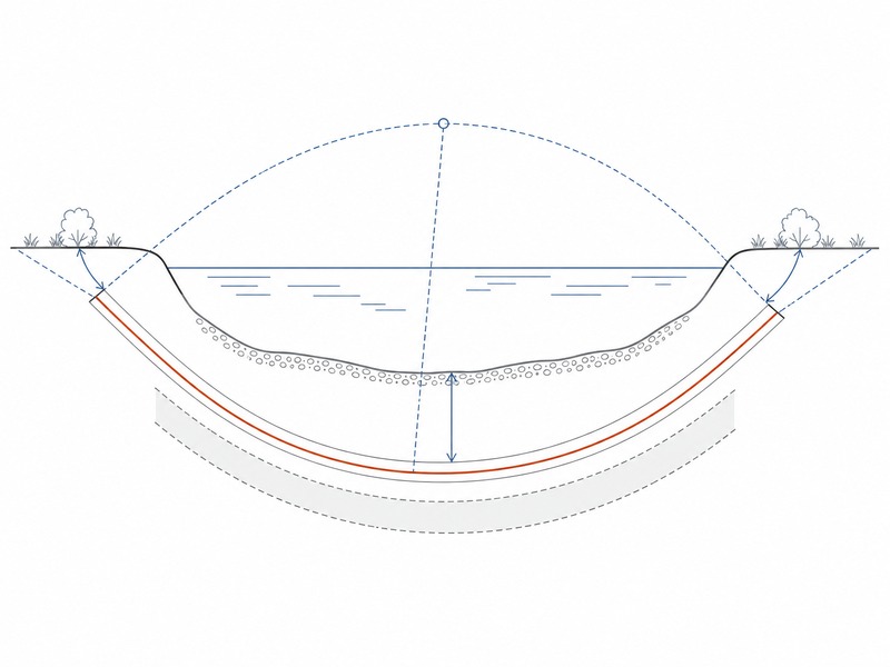
The governing check is that the calculated curvature of the alignment stays inside the allowable bend radius of both the drill pipe and the product pipe. Entry angle, exit angle, cover, bend radius and length are one connected problem. Published practice puts entry and exit angles in the 8° to 18° band for typical crossings, and a common planning rule of thumb for setback in a directionally straight profile is 5:1, meaning five units of horizontal setback per unit of depth. That ratio derives from the effective bend radius of the drill pipe or the product pipe. These are planning aids only; the alignment must be confirmed by calculation for the actual pipes and the ground present.
Pillar 2: Product pipe stress
The governing check is combined tension and bending during installation against the allowable stress of the pipe. The pipe must survive installation and then perform in service. Installation brings tension, bending and sometimes compression; service brings pressure, temperature and soil loading. ASTM F1962, the standard guide for maxi-HDD placement of polyethylene pipe and conduit under obstacles including river crossings, is the usual framework for the installation case, with ASCE Manual of Practice 108, Pipeline Design for Installation by Horizontal Directional Drilling, supporting the pipeline side. Both require project-specific calculation.
The editions in force at the time of writing are F1962-22 and the more recent F1962-25; a revision work item (WK93768) proposes an 8% deflection limit across DR ratings for both pressurised and non-pressurised pipe, so the edition should be confirmed before design. The load components behind the installation case are set out in our HDD pullback load and stress analysis guide, and the investigation scope behind the geotechnical profile in our HDD geotechnical investigation guide.
Pillar 3: Drilling fluid and inadvertent return
The governing check is whether drilling fluid returns are contained along the whole alignment. Drilling fluid must clean the hole, stabilise it and carry cuttings out, while staying where it was pumped. The design question is where fluid goes when it leaves the bore annulus. Sand and gravel with good permeability, shallow cover, and fracture paths in rock are the classic loss scenarios. Feasibility should identify those zones from the geotechnical profile and set the containment and response plan before construction.
Pillar 4: Constructability
The governing check is whether the entry and exit working areas can hold the rig, the pits, the crane positions and the full pipe string. Constructability belongs inside horizontal directional drilling design from the first iteration, because a geometry that cannot be staged, welded, buoyed and pulled is not yet a design. It covers the pipe string and staging area, welding and coating in the string, buoyancy control during pullback, crane positions for large-diameter pipe, pit dimensions and shoring, fluid mixing and recycling footprint, traffic management, and restoration duties. On urban crossings we have supported, the constraints at each end of the bore frequently drove the final geometry more than the geology did.
Where Is HDD Crossing Design Usually Won or Lost?
HDD crossing design most often fails on geometry, where several independent limits must be satisfied at once. The governing check is calculated curvature and cover against the allowable bend radius of the drill pipe and the product pipe; the published angles, ratios and cover figures are planning aids only, and each must be confirmed by calculation for the crossing.
- Cover: buried crossing cover is commonly specified between 0.9 and 1.5 m, with published HDD project reviews around a cover-to-diameter ratio of 1.5. Under watercourses, cover is set by scour and bed stability rather than a fixed figure.
- Curvature: as planning aids, drill pipe radius is often estimated at roughly 100 to 200 ft per inch of pipe diameter, and HDPE product pipe at about 25 to 35 times its outside diameter.
- Depth and guidance: walkover locating is practical to roughly 9 to 12 m in favourable conditions; deeper bores need wireline or gyroscopic steering, changing the accuracy budget.
- End areas: entry and exit angles must be achievable within the available setback, with room for the rig, pits and pipe string.
Success Criteria to Fix Before the Go or No-Go Decision
Five success criteria are fixed at feasibility and held through construction: tie-in tolerance, cover compliance, pipe integrity evidence, cost certainty, and restoration and landowner acceptance. Success is easier to define before design than to argue about afterwards.
With criteria agreed, the HDD feasibility study produces a recommendation rather than a debate.
- Tie-in tolerance, stated numerically for horizontal and vertical position and verified by as-built survey.
- Cover compliance along the crossing, under the feature and at the approach banks.
- Pipe integrity evidence: coating condition, weld records and installation load records.
- Cost certainty, with risk items priced explicitly rather than wrapped into contingency.
- Restoration and landowner acceptance, including fluid containment and reinstatement.
How Should the Go or No-Go Table Be Read?
The screening table below tests a crossing against the four feasibility questions raised above and states the residual risk that survives each verdict; it screens options for discussion and does not replace project-specific calculation.
Residual risk is stated relative to design and price: Low means the item is closed by standard design; Medium means it changes the fluid plan or the contingency; High means it can change the method or the route.
| Condition found at feasibility | Verdict | Why | Residual risk |
|---|---|---|---|
| Long watercourse crossing, good cover, competent soils | Proceed to design | Geometry and cover achievable with standard tooling | Low; confirm scour depth |
| Length beyond proven rig capability | Stop or re-scope | Pull load and rig margin cannot both be met | High |
| Thin cover over shallow rock | Stop or re-route | Rock reams slowly and cover cannot be increased locally | High |
| Cobbles and boulders, no fine-grained layer | Investigate further, then re-design | Steering becomes unpredictable and fluid loss likely | Medium to high |
| High artesian groundwater head | Proceed with caution | Inflow and lost returns change fluid and pit design | Medium; manageable with containment |
| Product pipe too stiff for available bend radius | Re-design | Pipe cannot follow the bore curvature | High |
This table screens options for discussion. It is not a substitute for project-specific engineering: verdicts depend on calculated loads, the actual geotechnical profile and the commercial context, and must be confirmed by a competent engineer before HDD crossing design is frozen.
What Should the Feasibility Stage Hand Over?
The HDD feasibility study should hand over a document set, not a conversation.
- Basis of design: standards, safety factors and load cases applied, with the geotechnical profile.
- HDD bore plan: plan and profile with stationing, entry and exit coordinates, centreline depth below ground and below the crossed feature, and curvature checks.
- Installation stress calculations: pullback load (pull load) components, allowable tension, combined tension and bending, buckling and collapse checks, and rig capacity margin.
- Drilling fluid plan: circulation design by stratum, containment, monitoring points and the inadvertent return response.
- Risk register: the output of the HDD risk assessment, listing each risk with an owner, a mitigation and a contingency.
The document set maps back to the four questions above: the HDD bore plan answers whether the geometry is achievable; the installation stress calculations and rig capacity margin answer whether it is drillable; and the drilling fluid plan, risk register and basis of design answer whether the risk and the commercial case are acceptable.
Where HDD Feasibility Studies Go Wrong
The failure patterns recur, and each is visible at feasibility stage when an HDD feasibility study is honest. In our design reviews, the two items most often missing when a review is first opened are the geotechnical characterisation profile and the verified utility potholes; either one sends the study back a step. Our field teams record the consequences months later, on site.

- Designing to a single borehole. One borehole across a 600 m crossing, an illustrative length, says little about the ground between the banks.
- Treating entry and exit angles as preferences. They are consequences of cover, setback and bend radius.
- Leaving the fluid plan to the contractor. Fluid loss is a design output; if it is not characterised, nobody is pricing it.
- Assuming the as-built will match the bore plan. Deviation is normal in long bores, so tie-in tolerances must absorb it.
- Comparing methods on capital cost alone. Restoration, permitting time and the cost of a lost-returns event belong in the HDD risk assessment.
Frequently Asked Questions
What is an HDD feasibility study?
An HDD feasibility study is a front-end engineering review that decides whether a crossing can be drilled, at what risk and at what cost range.
How long does an HDD feasibility study take?
Two to six weeks is typical for a crossing of moderate length and complexity once the survey and geotechnical data are in hand. The variable is rarely engineering time; it is how long the survey, geotechnical investigation and utility records take to obtain.
What information do I need to send for an HDD feasibility review?
Send the route survey and crossing limits, product pipe data, geotechnical logs from the HDD site investigation, utility records and the site constraints at both ends of the crossing. Missing geotechnical data is the most common reason a review has to be reopened.
Can HDD be used for any pipeline crossing?
HDD suits some pipeline crossings and not others; ground conditions, geometry, pipe stiffness, site footprint and drilling fluid management set the envelope. HDD suits long watercourse crossings and congested corridors, where the cover and geometry needed to avoid open cut are achievable. For short, shallow crossings in difficult ground, open cut and other trenchless methods usually compare favourably on cost and risk.
What is the most common reason an HDD crossing runs into trouble?
Underestimating ground conditions, and freezing the design before the geotechnical profile is understood. Lost fluid returns, stuck tooling, damaged coatings and excessive pull load usually trace back to assumed rather than measured conditions.
When should HDD be ruled out early?
HDD should be ruled out early when ground conditions or geometry make the bore technically or commercially unreasonable, for example shallow rock with thin cover, cobble and boulder zones, high artesian flow, or crossings short enough that open cut is cheaper.
Key Takeaways
- An HDD feasibility study is a decision gate, not a formality: it settles drillability, geometry, risk and method choice before money is committed.
- Its value is limited by its inputs; the survey profile and geotechnical profile do most of the work.
- Geometry, pipe stress, drilling fluid and constructability are one connected problem.
- Fix tie-in tolerance and cover compliance as success criteria before design starts.
- Published angles, ratios and cover figures are planning aids; confirm every value by calculation for the specific crossing.
- An honest no-go decision at feasibility is cheaper than a reworked crossing in construction.
How JSW Supports HDD Feasibility and Design
JSW is a pipeline engineering and construction company that plans and executes trenchless crossings with its own engineering team, crews and equipment. Our scope covers HDD crossing services and trenchless technologies. It extends to automatic pipeline welding, pipeline cold bending and layanan pemasangan pipa, so a feasibility verdict carries straight into delivery.
Because the same team carries out the horizontal directional drilling design review and then builds the crossing, our design basis reflects what the equipment and crews can achieve. We price risk items explicitly, publish the engineering basis behind our recommendations, and provide as-built records. Where HDD is the wrong method, we say so at feasibility rather than after mobilization.
- Integrated delivery: survey interpretation, bore plan, stress checks, pipe string fabrication and pullback under one scope, removing interface risk between designer and constructor.
- Auditable engineering: calculations, fluid plans and installation records are documented for construction review and later integrity management.
- Risk-explicit pricing: contingencies and their triggers are stated rather than absorbed into a lump sum.
- Crossing experience: watercourse, road and rail crossings and congested urban corridors, with permitting and restoration inside the scope.
Not sure whether your crossing is feasible? Send your route survey and crossing limits, geotechnical logs, pipe data and site constraints for a free technical review and HDD risk assessment. Our engineers respond with a scoped recommendation and a budget range.





































 English
  Arabic
  Russian
  Spanish
  French
  Vietnamese
  Polish
  Thai
Thai  Indonesian
  Turkish
  Portuguese