
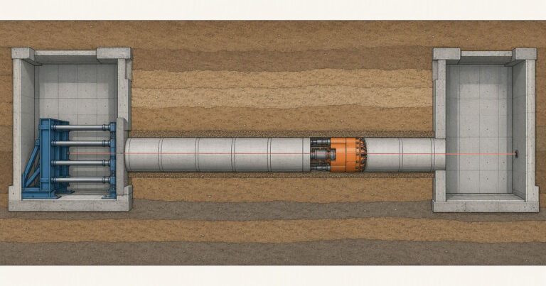
The short answer to how does microtunneling work is this: a remotely controlled, guided boring machine is jacked through the ground from a launch shaft to a reception shaft, excavating and supporting the face while the permanent pipe string is pushed in behind it, so the pipe becomes the finished tunnel lining. The sequence runs as eight linked stages, from the geotechnical investigation and drive design to the as-built survey.
The one-sentence answer hides a long sequence: the ground model, the shaft and thrust wall, the face support pressure, the lubrication regime and the guidance system all have to agree. The eight stages below follow one drive from the first borehole to final restoration.
Microtunneling applies to drives from about 0.35 m to 4 m (roughly 14 in to 13 ft), too small for a person to enter, so the machine is remotely operated. The figures come from published Pipe Jacking Association guidance, ASCE/CI 36-15 and EN 12889, and must be confirmed against your ground.
How Does Microtunneling Work? The Drive Sequence at a Glance
A microtunneling process runs as eight linked stages that hand conditions to each other. Each stage hands conditions to the next, and a weakness in any one shows up later as high jacking force or lost line and grade.
| Stage | What happens | Typical duration driver | What the owner signs off |
|---|---|---|---|
| 1. Investigation and drive design | Boreholes and testing define ground, groundwater and obstructions; drive length, diameter, machine and jacking limits are chosen. | Borehole spacing, ground variability, permits | Ground model, machine selection, risk register |
| 2. Shaft construction | Launch and reception shafts are excavated and lined; the thrust wall and pipe cradle are built. | Shaft depth, ground and water, lining | Shaft design, thrust wall capacity, settlement plan |
| 3. MTBM setup | Machine is lowered, aligned and connected; the entry seal is fitted. | Shaft size, seal type, services | Setup checklist, seal integrity, start alignment |
| 4. Launch and excavation | Machine launches; the closed face excavates and spoil leaves by slurry or auger. | Ground type, drive length, cutterhead | Launch approval, face support parameters |
| 5. Pipe jacking | Pipe string is jacked forward; the annulus is lubricated; interjack stations are added. | Drive length, friction, diameter | Jacking force limits, lubrication plan |
| 6. Guidance checks | Laser, theodolite, water leveling or gyro confirms line and grade. | Drive length, curve, ground | Alignment records against tolerance |
| 7. Reception and recovery | Machine enters the reception eye and is recovered. | Eye preparation, water head, exit alignment | Break-in plan, recovery completion |
| 8. Verification and restoration | Joints and coating inspected; annulus grouted; as-built survey and surface restored. | Inspection scope, grout volume, reinstatement | As-built records, restoration acceptance |
Duration tracks meters and shifts rather than diameter: the same advance rate covers roughly thirteen times the machine time on a 2,000 m drive as on a 150 m drive, before shaft and setup time is added.
Which stages overlap is a schedule decision. Shaft construction and machine mobilization run in parallel with the investigation report; guidance checks run continuously inside the jacking stage; and annular grouting follows joint verification, because grouting a damaged joint hides it.
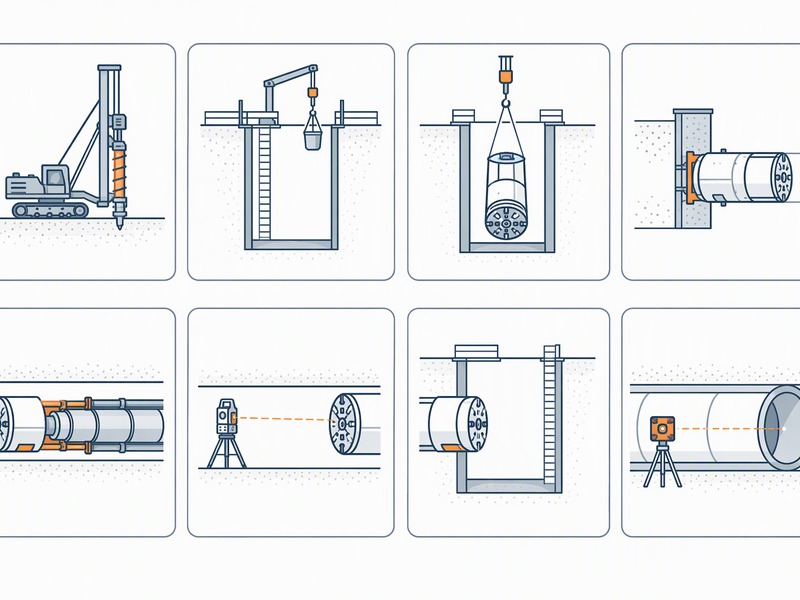
Step 1: Geotechnical Investigation and Drive Design Set the Envelope
Everything that follows is limited by the ground model. Investigation establishes soil and rock type, groundwater head, permeability, abrasiveness and obstructions such as boulders, old foundations or live services. The ground model decides the machine, the face support method, the cutterhead tooling and the jacking force the shaft resists. The answer to how does microtunneling work starts in the ground.
The investigation also fixes the drive envelope. Pipe Jacking Association guidance links achievable length to diameter, from about 150 m at diameters under 0.9 m to roughly 2,000 m at 2.4 m; longer drives demand more boreholes, interjack stations and a conservative force allowance. Eurocode 7 and BS 5930 frame the characterisation.
- Ground: soil and rock type, strength, abrasiveness, grading and groundwater head.
- Geometry: drive length, diameter, depth, curve radius and settlement-sensitive assets.
- Limits: calculated jacking force, permitted settlement and line-and-grade tolerance.
Step 2: Launch and Reception Shafts, Thrust Wall and Cradle
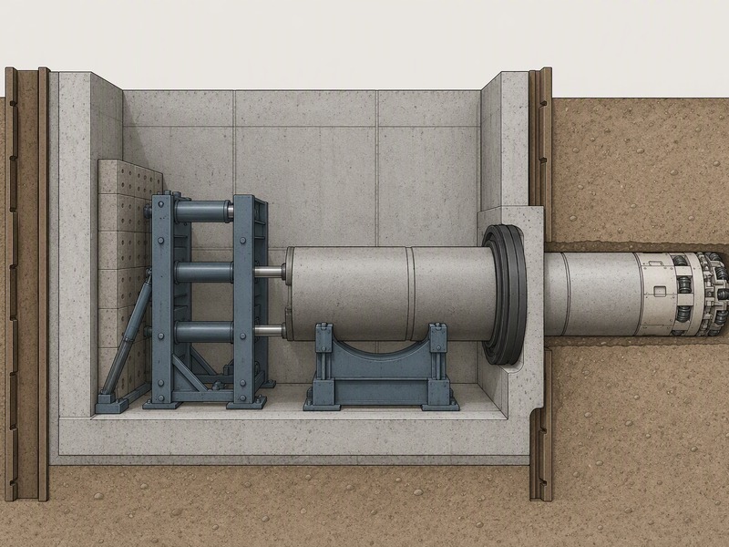
Shafts are the reaction points of the drive. The launch shaft carries the jacking frame, pipe cradle and thrust wall; the reception shaft carries the exit eye. Precast caisson shafts from about 2.4 m to 4 m suit microtunneling, and Pipe Jacking Association shaft tables cover dry ground to roughly 15 m with sheet piling and about 20 m with secant piling.
The thrust wall transfers jacking force into the ground. The rams push the pipe string forward and the frame pushes back against the wall, so wall and ground resist hundreds of tonnes on a long, high-friction drive. An undersized thrust wall lets the shaft move, and the line-and-grade datum moves with it. The cradle holds the machine and first pipe at design line and grade.
The reception eye’s depth and water conditions set how much work goes into controlling breakthrough.
Step 3: MTBM Lowering, Setup and the Entry Seal
With the shaft ready, the microtunnel boring machine (MTBM) is lowered onto the cradle and set to line and grade. The jacking frame is aligned behind it, and power, control, guidance and slurry lines are run to the surface cabin.
The entry seal is critical: the headwall carries a flexible seal or gland that closes around the pipe as it enters the ground and stops groundwater and slurry escaping the shaft. A leaking seal drops the face pressure, so it is pressure-tested before launch is authorised.
Launch is a controlled start. The machine enters at low force so the cutterhead meets the ground evenly and guidance confirms the first meters match design.
Step 4: Launch, Steering and Closed-Face Excavation
The machine excavates the face while the pipe advances behind it. In slurry machines the cutterhead works inside a closed plenum of pressurized bentonite slurry, which balances groundwater and earth pressure and carries cuttings to a separation plant. Auger machines remove spoil with a cased screw conveyor and suit stable ground where face support demand is lower.
Slurry pressure balance is the core control loop. Pressure must sit just above groundwater and earth pressure: too low and the ground runs in, causing over-excavation and settlement; too high and slurry escapes into permeable ground or lifts the surface. The operator balances this with slurry density, flow and advance rate. Here the answer to how does microtunneling work becomes visible at the face.
Steering is continuous. Articulation jacks let the machine turn slightly, and the operator makes small early corrections rather than large late ones. A typical overcut of 13 to 38 mm (about 1/2 to 1.5 in) gives the pipe room to follow the machine and the annulus somewhere to hold lubricant; that same gap is where ground can move. On road and rail crossings the overcut is narrowed so surface settlement stays below about 10 mm, whereas an overcut left at 35 mm in loose ground is itself enough to promote settlement.
Step 5: Pipe Jacking, Annular Lubrication and Interjack Stations
Pipe jacking is the force-transmission system of the method, and the part of the answer to how does microtunneling work that most readers picture first. The rams push the pipe string forward, and the force climbs with distance because friction acts along the external circumference. Pipe Jacking Association guidance puts jacking friction between about 0.5 and 2.5 tonnes per square meter of external area, and notes lubrication can cut it to as little as 0.1 tonnes per square meter.
Lubrication is a planned system. Bentonite slurry is injected through ports in the pipe into the annular gap, where it lubricates the pipe and helps stop the overcut void collapsing. Injection volume and pressure are controlled from the surface for the whole drive.
On long drives, lubrication is combined with interjack stations: stations at intervals in the pipe string carry their own rams and push only the pipe ahead of them, so force is distributed instead of concentrating near the launch shaft. JSW deploys them roughly every 100 to 150 m, with spacing set by the calculated jacking force, pipe strength and expected friction.
Jacking force is monitored against a calculated limit. A steady rise is normal as the string lengthens; an unexpected jump usually means changed ground, a lubrication problem or developing misalignment. In our experience, drives pushed hard to recover lost time later show packer damage. The jacking-force components are covered in our terminology guide.
What Happens When Jacking Force Rises Faster Than Predicted?
Stop and diagnose against the calculated limit instead of pushing harder.
Step 6: Guidance Checks and Line-and-Grade Correction
Guidance keeps the drive on design by reading a laser target in the machine against a theodolite or total station in the launch shaft, and steering the articulation jacks from it. Curved, long or deep drives add water leveling or gyro systems.
Tolerance is set before the drive starts. Pipe Jacking Association guidance gives a typical tolerance of plus or minus 50 mm (±50 mm) of true line and level at any point in stable, self-supporting, homogeneous ground, and warns finer tolerances may not be attainable in unstable ground or where obstructions occur.
Our field teams record the target reading and corrected heading at set intervals, and treat a slow drift as more dangerous than a sharp one, because late correction can mean over-steering that opens the overcut.
Step 7: Reception, MTBM Recovery and Break-In at the Reception Eye
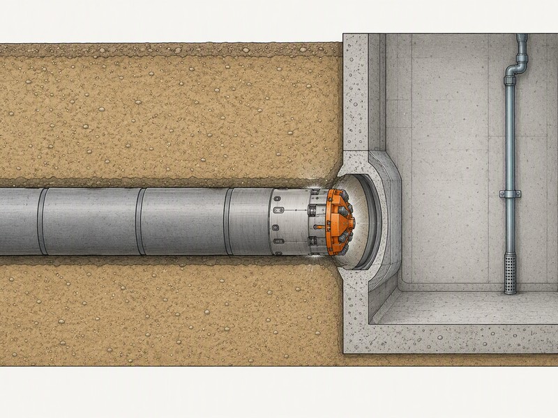
Reception is the closing stage of the microtunneling process: the machine approaches the prepared eye, the cutterhead passes through, and the machine is disconnected and lifted out.
Break-in to the reception eye is the highest-risk moment of the drive, and the point at which the answer to how does microtunneling work is most exposed. Three hazards arrive at once: the machine meets groundwater, it meets the shaft wall and its seal, and it arrives on an alignment that may have drifted by tens of millimeters over hundreds of meters. Seal the reception eye and control the water head before the machine enters the last meters: with both in place the face stays supported and the shaft stays dry.
Controls are consistent: the last meters are advanced slowly at reduced force, and groundwater is managed by dewatering or controlled pressure. We have seen reception shafts flooded when the eye seal was treated as a formality; recovery is slow and costly.
How Is the Reception Eye Prepared Before Break-In?
The eye is set to the true arrival line, sealed or fitted with a gland, and dewatered where the water head is high.
Step 8: Joint and Coating Verification, Backfill, As-Built Survey and Restoration
The microtunneling process continues after the machine is out: joint integrity, the annulus and the as-built record all have to be closed out. Joint integrity and coating are verified along the string, because jacking force and misalignment concentrate stress at the joints. Jacking pipe is specified and tested to standards such as EN 1916, BS EN 295-7 and BS 5911-1, and inspection confirms the installed pipe still meets joint performance.
The annulus is then treated: the overcut gap is grouted where the design requires it, to fill the void, lock the pipe and limit further ground movement. Shafts are backfilled or sealed and temporary works removed.
Finally, an as-built survey records the actual line and grade, pipe invert, joint positions and any deviation, and the surface is restored. The as-built record is what later inspection and maintenance depend on, so it should settle where the pipe is. The inspection scope itself is covered in our terminology guide under verification terms.
Failure Modes in a Microtunneling Drive and How They Are Mitigated
Face support pressure and jacking force decide the answer to how does microtunneling work in practice. Most problems fall into a few recognisable modes, each with a mitigation that belongs in the method statement.
| Failure mode | Typical trigger | Consequence | Mitigation |
|---|---|---|---|
| Face instability or collapse | Loose or cohesionless ground; pressure too low | Over-excavation, ground loss, settlement | Balance pressure to ground and water; correct slurry density; slower advance |
| Excessive jacking force | High friction, long drive, weak lubrication | Pipe or joint damage, thrust wall overload | Annular lubrication, more interjack stations, force monitoring |
| Loss of line and grade | Steering lag, soft or mixed ground, obstruction | Out-of-tolerance bore, rework | Frequent guidance checks; small early corrections; gyro in long drives |
| Slurry loss to ground | Permeable ground; over-pressure | Face support collapse, settlement or heave | Match pressure to ground; add polymer; monitor returns |
| Settlement or heave | Wide overcut, ground loss, excessive pressure | Damage to roads, rail and buried assets | Reduce overcut on sensitive crossings; control pressure; monitor |
| Cutterhead wear | Abrasive ground over a long drive | Slow advance, unplanned intervention | Predict wear; select harder tooling; plan inspection stops |
| Reception eye breakthrough | High water head, poor eye preparation, alignment drift | Flooding, loss of face, ground loss | Sealed or dewatered eye; reduced force in the last meters |
Two failure modes carry most of the cost and risk: loss of face support at the cutterhead, and breakthrough at the reception eye. Both are designed long before the machine is lowered.
Frequently Asked Questions About the Microtunneling Process
Most of these questions come from owners who want the answer to how does microtunneling work on their own alignment.
How long does a single microtunneling drive take?
Most drives take days to months, on a schedule set by meters and shifts rather than by diameter. Duration is driven by drive length, diameter, ground conditions and the number of shaft setups; Achievable length rises with diameter, and Table 1 gives the indicative figure for each size class; anything beyond 1 km needs project-specific risk analysis.
How does the machine know it is on line and grade?
Guidance comes from a laser target carried in the machine and read against a theodolite or total station in the shaft. The operator reads the target and steers the articulation jacks; curved, long or deep drives add water leveling or gyro and inertial systems. Pipe Jacking Association guidance gives a typical tolerance of plus or minus 50 mm of true line and level in stable ground.
Why does slurry pressure matter during excavation?
Slurry pressure balances groundwater and earth pressure at the face. If the pressure is too low the ground flows in and causes settlement; if it is too high the slurry escapes into the ground or heaves the surface. The operator controls it by tuning slurry density, flow and advance rate.
How accurate is microtunneling?
Typical published tolerance is plus or minus 50 mm of true line and level in stable ground. Pilot tube microtunneling is quoted as within plus or minus 1 inch (about 25 mm) of design grade and plus or minus 3 inches (about 75 mm) of alignment. Tighter tolerances are harder in unstable ground or where obstructions are met.
Why is breakthrough at the reception eye the riskiest step?
Breakthrough is risky because the machine meets groundwater, the shaft wall and an alignment that may have drifted. If the reception eye is not sealed or the water head is not controlled, the face can flood and the ground can run. The last meters are advanced slowly with reduced force until the cutterhead enters the eye cleanly.
Can a Microtunneling Drive Pass Under a Live Railway Without Stopping Trains?
Yes, when settlement is controlled, not when diameter alone is small. Under a live railway the overcut is narrowed so surface settlement stays below about 10 mm, whereas an overcut left at 35 mm in loose ground is itself enough to promote settlement.
What Has to Be True Before a Drive Under a Buried Service Line Can Launch?
Three conditions have to be true: the ground model is confirmed, the shaft and thrust wall can take the reaction, and the entry seal holds pressure. Launch follows only after all three are signed off.
Key Takeaways
- How does microtunneling work in practice? The process is a chain of eight dependent stages, from the ground model to the as-built survey.
- Face support pressure and jacking force are the two control loops that keep ground and pipe in place.
- Lubrication is a planned system, not a reaction: injection is controlled from the surface for the whole drive.
- Tolerance is set before launch, and the guidance log records the drift that matters more than any single reading.
- Break-in at the reception eye is the highest-risk moment, because groundwater, the shaft wall and alignment drift arrive together.
How JSW Supports Your Microtunneling Drive
JSW is a pipeline engineering and construction company that executes trenchless crossings with its own crews and equipment. Our scope covers microtunneling construction, trenchless technologies, layanan pemasangan pipa, pipeline inspection services and pipeline repair services, so investigation, installation, verification and follow-up sit under one team. Whether you are testing the process behind how does microtunneling work for a feasibility study or checking a contractor’s method statement, one scope keeps the sequence accountable from shaft to breakthrough.
We plan drives around the conditions, not a template, and ground risk is priced openly. Our teams install DN300 to DN1500 (12 to 60 inch) lines by microtunneling, with drives up to 600 m, laser guidance of ±25 mm, depths of 2 to 25 m and ground capability from soft clay to cobbles, mixed ground and rock up to about 80 MPa UCS. JSW holds ISO 9001:2015, ISO 14001:2015 and ISO 45001:2018 certification.
- Integrated delivery: investigation, shaft works, microtunneling, verification and restoration under one contract.
- Auditable process data: jacking force, guidance and face support records kept for the owner.
- Risk-explicit pricing: ground-related risk named and priced, not hidden in a contingency.
- Safety and compliance: confined-space and shaft works managed to OSHA and UK CDM practice.
Want the answer to how does microtunneling work applied to your own alignment? Send your route, drive length, diameter and geotechnical report for a free technical review. Our engineers reply with a step-by-step sequence for your alignment, the three stages we would flag as highest risk, and an indicative budget range.





































 English
  Arabic
  Russian
  Spanish
  French
  Vietnamese
  Polish
  Thai
Thai  Indonesian
  Turkish
  Portuguese