
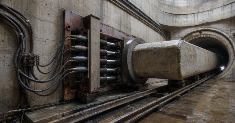
A jacking frame converts hydraulic power into the forward thrust that drives a microtunneling machine and its pipe string, and it is only as strong as the load path behind and ahead of it. It sits on line and grade in the launch shaft, reacts against a thrust wall (also called the reaction wall, or a thrust block in some specifications), and pushes the machine and pipe string through the ground one pipe at a time. Around it sits support equipment – thrust rings, spacers, guide rails, intermediate jacking stations and load monitoring – that decides whether the force reaches the lead pipe evenly or destroys it. In this guide the thrust ring is the load-distribution ring on the frame, and the thrust wall is the structural reaction behind it; the two are not interchangeable.
This guide follows the load path from ground reaction to lead pipe, explains what each item in that path has to do, how a jacking frame is sized and lined up, why thrust ring rigidity is the whole point, how intermediate jacking stations are spaced and built, what pipe spacers do, how load monitoring turns thrust into usable data, and which failure modes to inspect for before the drive starts.
What Has to Carry the Jacking Force?
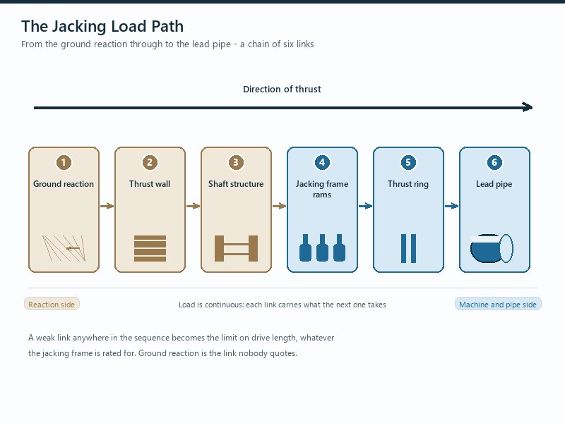
The jacking force is carried by six interfaces in series – the ground behind the reaction, the thrust wall, the shaft structure, the jacking frame and its rams, the thrust ring, and the lead pipe – and the weakest of them sets the drive limit. A frame rated above the interfaces behind and ahead of it adds no usable capacity: the limit simply shifts to the weaker element.
Specify the support equipment as one chain, not as separate purchases: the reaction, the wall, the frame, the ring and the pipe must all be checked against the same friction figure and the same margin. In our bid reviews, the most common structural mistake is a frame with generous thrust capacity checked against a thrust wall and a lead pipe that were never sized against the same number.
This page covers the load-path hardware, not the jacking-force calculation, which is a separate design step.
The Load Path: Thrust Wall to Lead Pipe
Each of the six interfaces in the jacking load path has a distinct job, and each fails in its own way. Reading the path in order is the quickest way to find where a drive is likely to be limited.
| Interface | What it has to do | Failure if under-designed |
|---|---|---|
| Ground behind the reaction | Absorb the reaction without yielding | Movement of the thrust wall, loss of stroke, cracked shaft |
| Thrust wall | Resist the anticipated jacking load and transfer it through the shaft structure to the surrounding ground | Local crushing, wall displacement, or shaft damage |
| Shaft structure and cradle | Carry the load and hold the frame on line and grade | Frame movement during jacking, alignment loss at launch |
| Jacking frame and rams | Develop thrust and keep it even across the pipe | Uneven thrust, lead pipe damage, no usable thrust record |
| Thrust ring | Distribute the ram load around the pipe circumference | Point loading, spalling or cracking of the lead pipe |
| Lead pipe and string | Transmit thrust to the machine and along the pipes | Joint damage, misalignment, and jammed strings |
Thrust Walls and Reaction Capacity: Where Bids Fail
A thrust wall exists to provide a reaction against which to jack, and it has to be designed to withstand the anticipated jacking load and transfer that load through the shaft structure into the surrounding ground. Where ground is poor, piling or other special arrangements may be needed to increase reaction capability. Where there is insufficient depth to build a normal thrust wall – through an embankment, for example – the reaction has to be resisted by a structural framework restrained with piles, ground anchors or similar load-transferring measures.
First, reaction capacity has to be checked against the same friction figure used to size the frame, because the wall holds its position only when it is sized on the same figure as the frame. Second, the thrust wall is a design item, not a site improvisation, which is why published specification practice treats the frame and the wall as design documentation subject to a hold point before work starts.
For a bidder, the practical test is whether the tender documents name the friction figure that both the reaction and the frame were sized against; if they do not, the number in the bid is not comparable with the number on site. For an owner or an EPC firm reviewing a method statement, the same question applies one level up: the reaction design has to be traceable to the same figure.
In our experience, reaction problems announce themselves early and in a characteristic way: the rams extend but the pipe does not advance as expected, and stroke is lost without any change in the ground. If the thrust wall can move, every other number on the drive becomes unreliable, because jacking force readings are being taken against a moving reference. Readings taken against a moving reference are not comparable with the design figure, so the frame, the thrust wall and the pipe string must all be confirmed against the same project-specific friction value by the machine supplier and a competent engineer.
Jacking Frames: Stroke, Tonnage, Grouping and Line-Up
Frame selection rests on thrust, stroke and even cylinder grouping.
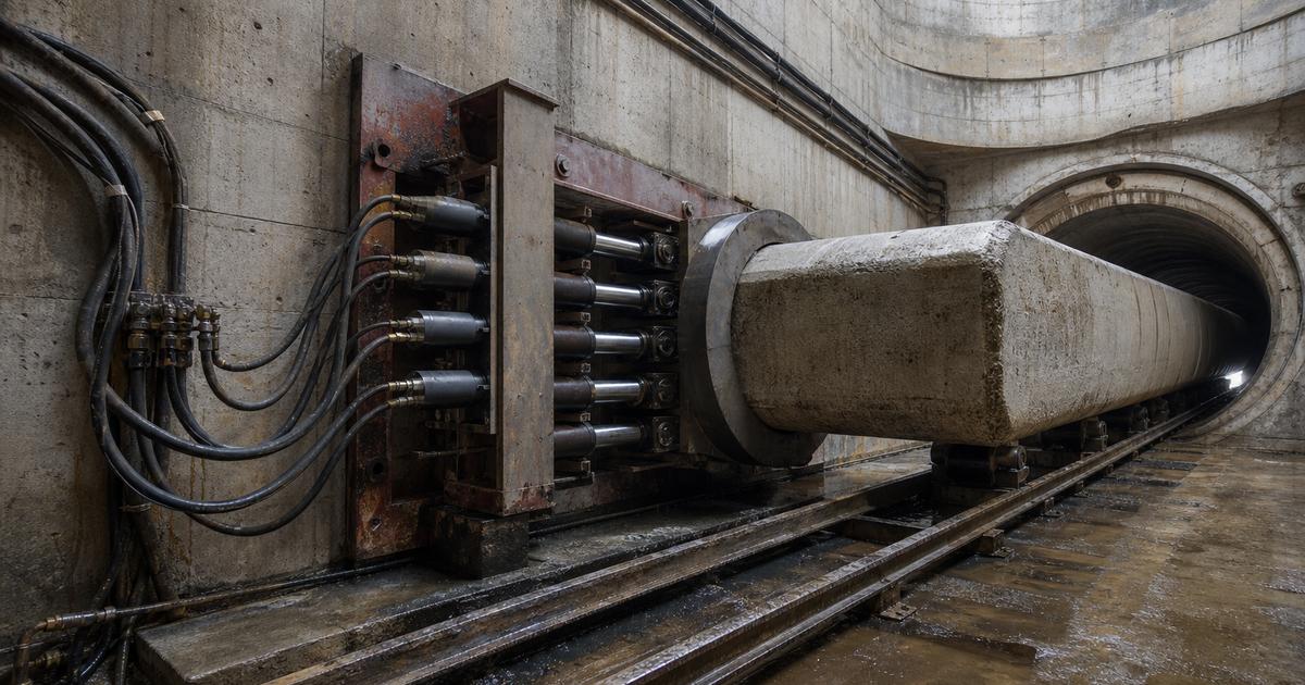
A jacking frame is sized to accommodate the machine, the pipe diameter and the specific needs of the project according to ground conditions and shaft length. It is positioned in front of the reaction wall on line and grade, and its horizontally mounted hydraulic cylinders advance the machine and pipe string – frames of this class are built with cylinders delivering up to about 1,200 t of thrust, with keyed notches that lock the cylinders in place to keep advancement smooth and continuous.
- Tonnage. Sized from the anticipated friction along the string plus an allowance for the ground the investigation did not find, not from the largest frame available; the friction figure itself is a project-specific design input, not a catalog value.
- Stroke. Set by pipe length and shaft dimensions.
- Grouping and evenness. The jacks are hydraulically interconnected so that the thrust from each is equal, and the number used varies with pipe size, pipe strength, drive length and anticipated frictional resistance.
- Line-up and guide rails. Guide rails accurately positioned within the thrust pit control the initial alignment of the pipe, and the machine and cradle are verified on line, grade and level before launch.
- Instrumentation. Each set of jacks in the launch pit is to carry suitably calibrated pressure gauges in good working order so actual jacking force can be read at any time, and the jacks are to measure thrust pressure, stroke position and stroke speed.
Thrust Rings and Load Distribution: Why Rigidity Is the Whole Point
Mounted on the frame, the thrust ring transfers the jacking load to the pipe and distributes it around the pipe circumference. It has to be sufficiently rigid to ensure even distribution of the load, and that requirement is where most thrust-related pipe damage originates.
A concrete jacking pipe is strong in uniform compression and comparatively weak against point loading or bending. If the ring deflects, the ram load concentrates at the pipe’s strongest local points and creates exactly the stress pattern the pipe was not designed for – which is why the visible failure is often a longitudinal or radial crack rather than a crushing of the pipe end. Even with an adequate ring, the load path depends on the pipes themselves being able to take the thrust: on long drives, uneven jacking loads and pipe misalignment are the recognized mechanism behind cracked pipes and jammed strings.
Bottom line: the thrust ring is a load-distribution device, not a consumable pad. If it is being replaced because it deforms, the force being applied to the lead pipe is higher than the pipe was designed to accept.
Intermediate Jacking Stations and Pipe Spacers
Intermediate jacking stations and pipe spacers solve two different problems: the first redistributes thrust along a long drive, and the second holds a carrier pipe centralized inside its bore or casing.
How Intermediate Jacking Stations Are Spaced and Built
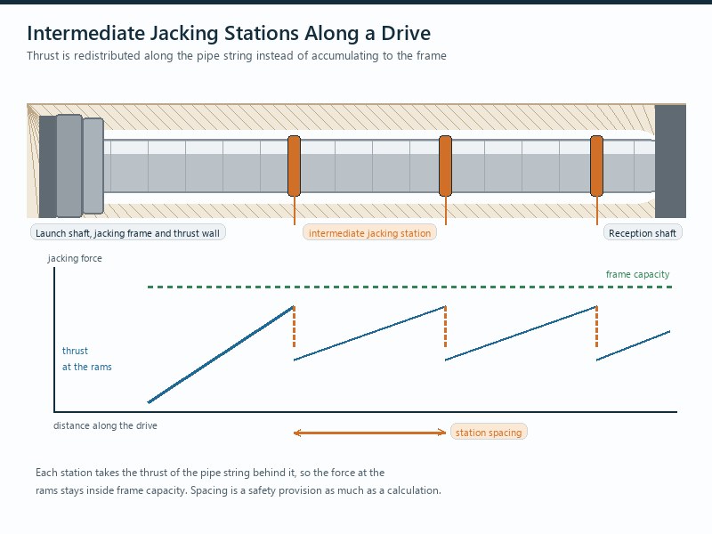
As a drive lengthens, friction accumulates and the thrust required approaches what the pipe string and the reaction can carry. Intermediate jacking stations solve this by redistributing the total jacking force along the pipeline rather than asking the launch shaft to supply all of it.
A station consists of a pair of modified jacking pipes with a special twin pipe set: an increased-length steel collar slides over a corresponding spigot, with hydraulic jacks between the two opposing pipes. When the design value is reached, or when available thrust is insufficient to move the pipeline, the pipes behind the station are held stressed back to the thrust wall and the station jacks are opened to advance the forward section. At the end of the stroke the main jacks advance the rear section and close the station jacks, and the sequence repeats.
| Parameter | Published practice | Why it matters |
|---|---|---|
| Spacing for safety | Ready-to-use stations roughly every 80 to 120 m, first station as close as practicable to the machine | Provides a fallback if lubrication partially fails and friction rises sharply |
| Specification allowance | One station every 100 m of drive length unless justified otherwise | Keeps the number of stations a design decision rather than a change order |
| Sleeve overlap | Steel sleeves overlapping the pipes by at least 150 mm on either side of the joint | Protects the joint and keeps the station sealed against ground and water |
| Minimum internal diameter | About 1,200 mm and above | Stations are fitted out from inside the tunnel, which requires man access |
| Operational readiness | All stations brought into readiness and driven a few centimeters, even when not actively supporting the drive | Lets each station’s force be measured and compared with the permissible force |
Pipe Spacers: A Design Item, Not an Accessory
Pipe spacers address a different problem. A carrier pipe installed inside a bore or a casing has to be carried and centralized, and the spacers doing that work are specified against a recognized product specification and an accepted civil products list. If an alternative spacer is proposed, drawings and calculations have to demonstrate that it suits all applied loads and has the durability for the required design life. In our experience spacers are treated as a minor purchase until a carrier pipe moves during installation, after which they are treated as a design item.
Load Monitoring, Failure Modes and What to Inspect
Thrust becomes useful information only if it is measured at the right places. Instrumenting the frame gives the total force at the shaft, but it cannot tell you where along the string the force is being consumed. Instrumenting each intermediate jacking station closes that gap.
Online load control compares the measured station force against a permissible jacking force derived from buckling measurement and load history, which is the established way to detect overloading before pipe damage occurs. The permissible value is project-specific and must be set by the equipment supplier and a competent engineer.
| Failure | Mechanism | Prevention |
|---|---|---|
| Reaction wall displacement | Reaction capacity below anticipated load, or poor ground behind the wall | Design the wall against the same friction figure as the frame; use piling or anchors in weak ground |
| Lead pipe spalling or cracking | Point loading from an insufficiently rigid ring, or ram load exceeding the pipe’s limit | Rigid ring; hydraulically equalized jacks; limit single-ram and combined-ram load |
| Pipe damage mid-string | Uneven jacking load and misalignment, often where a jammed pipe concentrates force | Monitor station forces; keep alignment corrections gradual within permitted joint deflection |
| Lost stroke without ground change | Frame or cradle movement under load | Verify set-out, cradle and guide rails before launch; re-check datum during long drives |
| Jammed string on a long drive | Lubricating film lost, fines compacting around the pipes | Ready-to-use interjack stations and continuous lubrication monitoring |
| Carrier pipe movement | Inadequate or non-compliant pipe spacers | Specify spacers to the product specification; document any alternative with calculations |
Key Takeaways
- A jacking frame supplies thrust but does not carry it alone: six interfaces in series share the load, and the weakest one limits the drive – which is why the reaction, frame and pipe string have to be sized against one figure.
- Frames of this class are built with cylinders delivering up to about 1,200 t of thrust, and the frame has to be sized from the friction the string is expected to develop.
- The thrust ring has to be rigid enough to distribute ram load evenly around the pipe circumference; the jacks are hydraulically interconnected to equalize thrust.
- Intermediate jacking stations are provided roughly every 80 to 120 m for safety, with a specification allowance of one per 100 m, and are practical at internal diameters of about 1,200 mm and above.
- Station sleeves should overlap the pipes by at least 150 mm either side of the joint and be sealed against pressurized ground and water.
- Pipe spacers and jacking force instrumentation are design items, not site accessories: both need to be specified before the drive, not during it.
Frequently Asked Questions
What does a jacking frame actually do?
The frame converts hydraulic power into thrust that moves the machine and the pipe string forward from the launch shaft. The frame is set on line and grade in front of the reaction wall, and the force it develops is transferred through a thrust ring into the lead pipe rather than into the pipe wall directly.
How is the thrust capacity of a jacking frame decided?
Thrust capacity is decided by the friction the pipe string is expected to develop, not by what happens to be available. Published Pipe Jacking Association guidance puts pipe jacking friction at 0.5 to 2.5 tonnes per square meter of external circumferential area, reducible to as little as 0.1 tonnes per square meter with good lubricant injection. The frame, the thrust wall and the pipes all have to be designed against the same figure.
Why is the thrust ring so important?
The ring spreads the ram load around the whole pipe circumference. With the jacks hydraulically interconnected so that each delivers the same thrust, a sufficiently rigid ring keeps the load even; an insufficiently rigid ring concentrates load and damages the lead pipe.
How often should intermediate jacking stations be installed?
Published practice supports ready-to-use stations roughly every 80 to 120 m for safety, with a specification-driven allowance of one every 100 m of drive length unless justified otherwise. The first station should be as close as practicable to the machine.
What limits where an intermediate jacking station can be used?
Fit-out access is the constraint. Intermediate jacking pipes are fitted out from within the tunnel, so they are practical only at internal diameters of about 1,200 mm and above. The sleeves forming the joint should overlap the pipes by at least 150 mm on either side and carry seals against pressurized ground and water.
What are pipe spacers for?
They carry and centralize a carrier pipe inside a bore or casing. Spacers are specified against a recognized product specification, and any alternative has to be supported by drawings and calculations showing they suit all applied loads and will last the design life.
How JSW Supports Jacking Set-Up and Load Control
JSW is a pipeline engineering and construction company that executes trenchless crossings with its own crews and equipment. Our scope covers microtunneling construction, trenchless technologies, HDD crossing services and layanan pemasangan pipa, and we run microtunneling drives of DN300 to DN1500 with single drives up to 600 m and interjack stations deployed roughly every 100 to 150 m on extended drives.
Because the reaction, the frame and the pipe string are designed by the same team that operates them, the thrust calculation, the thrust wall design and the station spacing are resolved together before mobilization, and the forces actually measured during the drive are kept as a record rather than discarded.
- Load path designed as one chain: reaction, wall, frame, thrust ring and pipe checked against the same friction figure and the same margin.
- Instrumented thrust: calibrated pressure gauges on every jack set and force readings at each intermediate jacking station, logged through the drive.
- Station provision planned, not improvised: interjacks allowed at defined intervals and brought into readiness so their forces can be measured.
- Certified delivery: our trenchless work is delivered under ISO 9001:2015, ISO 14001:2015 and ISO 45001:2018 certified management systems.
If any of the six interfaces is unverified, the drive is unverified.
Preparing a bid or a long-drive jacking set-up? Send the friction figure your tender assumes, your pipe diameter, drive length, alignment and geotechnical summary for a free technical review. Our engineers respond with a scoped support equipment recommendation and an indicative budget range.





































 English
  Arabic
  Russian
  Spanish
  French
  Vietnamese
  Polish
  Thai
Thai  Indonesian
  Turkish
  Portuguese