
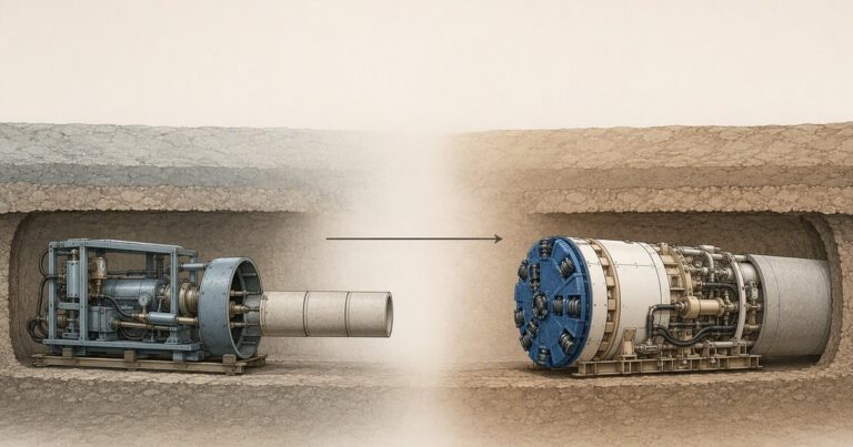
The history of microtunneling begins in early-1970s Japan, where engineers needed to install and replace gravity sewers under congested city streets without cutting them open. It spread across Europe and the United Kingdom through the 1970s and 1980s, reached North America in the early 1980s, and matured into a standards-based method. The first North American project is dated 1983 by one research source and 1984 by several others, and this page keeps that dispute open rather than resolving it.
Why Did Microtunneling Emerge in Early-1970s Japan?
The opening chapter of the history of microtunneling belongs to Japan. Microtunneling was developed to install gravity sewers under streets that could not be opened to traffic.
Two pressures shaped the method: dense traffic and buried utilities made open-cut trenching disruptive, and gravity sewers demand accurate grade over a long distance. The answer was a remotely operated machine that carried a cutterhead, held line and level with a guidance system, and drew jacking pipe behind it.
The equipment lineage is usually traced to Japanese manufacturers. Iseki Poly-Tech, Inc., of Tokyo, was established in 1971 and built a global reputation for tunnel boring and trenchless equipment. Its UNCLEMOLE microtunneling system has been in the market for more than four decades.
A caution belongs here. Public accounts credit Japanese development of slurry microtunneling in the mid-1970s, but the record does not support naming a single inventor. The honest reading is that microtunneling emerged across a small group of Japanese firms and demonstration projects, with Iseki and the UNCLEMOLE range among the best documented names from that period.
A Timeline of Microtunneling: Documented Milestones and Disputed Dates
Any history of microtunneling has to separate three kinds of evidence: published company and standards records, single-source research, and oral history repeated in trade articles. The table labels each milestone so a reader can see which claims are firm and which remain tradition. The record type sets the level: dated publications documented, single research sources provisional, uncited trade stories tradition.
| Period | Milestone | Evidence status |
|---|---|---|
| Early 1970s | Method developed in Japan to install gravity sewers and replace open sewers in urban areas with underground gravity sewers | Documented in published industry history |
| 1971 | Iseki Poly-Tech, Inc., Tokyo, established | Documented as a company record |
| Mid-1970s | Public accounts credit Japanese development of slurry microtunneling | Industry account; no primary machine record established |
| 1970s onward | Microtunneling in use across Japan and Europe | Documented; no single arrival year for Europe |
| Early 1980s | First US project: 600 ft (about 180 m) of 72-inch (about 1,800 mm) pipe under I-95 and the FEC Railroad | Date disputed between 1983 and 1984 |
| Mid-1980s | Iseki closely linked to microtunneling in the United States | Documented |
| 1989 | One transportation research source records 14 US microtunneling projects completed as of 1989 | Documented from a single source |
| April 2015 | ASCE/CI 36-15, Standard Design and Construction Guidelines for Microtunneling, published | Documented standard |
| Around 2015 | Iseki re-enters the North American market | Documented market account |
| September 2025 | Akkerman, based in Iowa in the United States, announces 30 years of microtunneling | Documented company announcement |
Read the table as a map of confidence, not only of dates: the first US project is the clearest disputed date, and the mid-1970s slurry development is an industry account, not a primary source. In our research reviews we treat disputed dates as ranges.
How Did Microtunneling Spread to Europe and the United Kingdom?
Microtunneling has been used in Japan and Europe since the 1970s, and the European chapter developed in parallel with the Japanese one rather than simply copying it. The United Kingdom and continental Europe adopted the method for sewers, culverts and utility casings where street works were unacceptable.
Adoption was uneven. Early European work concentrated on soft ground and short drives, because machine power and guidance were still developing.
Europe’s lasting contribution was institutional. The Pipe Jacking Association in the United Kingdom published guidance on machine types, jacking lengths and tolerances. European standards gave owners a shared language for trenchless sewer construction and testing. BS EN 12889 and EN 1916 are part of the history of microtunneling because they made the method procurable and comparable between bidders.
One date is genuinely open: no single year marks microtunneling’s arrival in Europe, and no primary record fixes a first European drive.
When Did Microtunneling Reach North America?
The first North American project is dated to the early 1980s, and that is where the record becomes contested. One transportation research source places the first US project in 1983 and records that 14 US microtunneling projects had been completed as of 1989. Several other sources date the milestone to 1984. Both descriptions point to the same job: a 600 ft crossing with 72-inch pipe under I-95 and the FEC Railroad in south Florida.
Because the accounts differ, this page states the dispute rather than resolving it: the first microtunneling project was completed in either 1983 or 1984 in south Florida.
The 1989 figure of 14 completed projects is more useful than the disputed year: it shows how slowly adoption began. In the wider history of microtunneling, the method arrived as a curiosity and became a market.
Iseki was closely linked to microtunneling in the United States by the mid-1980s, which places Japanese equipment at the center of the early North American market. Iseki later re-entered the North American market around 2015, a gap and return that is itself part of the equipment story.
How Did Interjack Stations and Bentonite Lubrication Extend Drive Lengths?
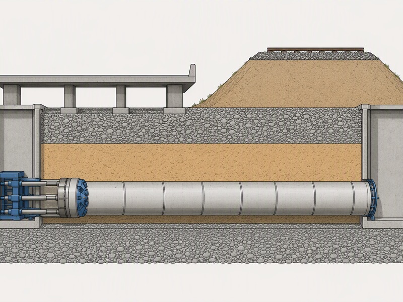
Early drives were limited by friction. As a machine and its pipe string lengthen, the jacking force climbs and the launch shaft’s thrust wall has to resist it; hundreds of tonnes of force may be required. Published Pipe Jacking Association guidance reports jacking friction of about 0.5 to 2.5 tonnes per square meter of external circumferential area.
Two developments changed the ceiling. Bentonite lubrication, injected into the annular gap around the pipe, can reduce that friction to as little as 0.1 tonnes per square meter. Intermediate jacking stations placed between pipe sections split a long string so no single section carries the whole load.
Lower friction plus interjack stations produced the long-drive era. Pipe Jacking Association guidance states that jacking lengths can be considerably in excess of 1 km depending on diameter, ground and excavation method, while adding that such lengths should only be attempted after project-specific risk analysis. Indicative figures rise with size, from around 150 m at diameters under 0.9 m to roughly 1,000 m at 1.9–2.1 m.
In our bid reviews, the presence of a lubrication and interjack plan is often the clearest signal that a long drive is being taken seriously. We have seen tender documents quote a long length without any statement of how thrust will be distributed.
From Open Face to Closed Face: Slurry, EPB and the Japanese-to-German Axis
Early machines were mechanically simple. Open-face and auger systems removed spoil with a screw and relied on the ground standing long enough to be cut, which struggled in water-bearing sands and gravels.
The shift to closed-face machines added face support. The Pipe Jacking Association describes microtunneling machines as typically of two types, pressurized slurry and auger, both having face support capability and remotely controlled from the surface. Slurry machines balance groundwater with a pressurized bentonite suspension and carry spoil to a separation plant. Earth-pressure-balance machines are used for larger pipe jacks, best in cohesive soils, conditioned with bentonite, water or polymer in mixed faces.
The equipment axis that followed is commonly described as running from Japan to Germany. Japanese firms pioneered the method, and European, especially German, machine builders industrialized it as the market widened, supplying complete systems, spare parts and service. The pattern of a few dominant suppliers is reported in trade accounts rather than as a single documented event. The outcome is not in doubt: buyers gained competing suppliers, and owners gained specialist contractors able to bid the method commercially.
A contractor and owner market with several qualified suppliers changed how projects were shaped. Once several suppliers could deliver a machine and several contractors could operate one, owners began writing the method into tender documents and comparing bids on reference drives and settlement control. Our field teams record that bid quality tracks with a contractor’s own jacking and lubrication data.
The Standards Era: ASCE/CI 36-15, PJA Guidance, BS EN 12889 and EN 1916
The era of microtunneling standards is the clearest dividing line in the history of microtunneling. Before it, practice lived in manufacturers’ manuals and contractors’ experience; after it, owners could specify the method and hold a contractor to published tolerances and procedures.
ASCE/CI 36-15, Standard Design and Construction Guidelines for Microtunneling, was published in April 2015. Its most quoted sentence states that microtunneling describes a method and does not impose size limitations on diameter. That sentence in ASCE/CI 36-15 reframed the “micro” label as a convention rather than a rule, and explains why machines of very different diameters are all described as microtunneling.
Alongside ASCE/CI 36-15 sit the Pipe Jacking Association guidance on machine types, jacking lengths and tolerances, European standard BS EN 12889 for trenchless construction and testing of new sewers, and EN 1916 for concrete pipes and fittings. Other documents support narrower parts of the work, including ASTM F1962 and BS EN 295-7. NASTT carries the North American side of that work as the region’s trenchless training and good-practice body.
Standards gave every drive a documented basis for tolerance and risk; they work alongside ground investigation, which decides whether the drive is predictable. What they did was give owners a defensible basis for specifying tolerance and risk, and contractors a shared vocabulary for bidding.
Curved Drives, Long Drives and What the Records Show
Two capabilities define the modern era: driving on a curve, and driving a long way. Curved drives became practical because jacking pipe joints allow controlled deflection. Published Pipe Jacking Association guidance notes that standard 2.5 m long pipes can be jacked to a radius of about 200 m, with shorter pipes reaching tighter curves within the pipe manufacturer’s permitted joint deflection.
Long drives developed in parallel. Indicative jacking lengths rise with diameter, and guidance notes that lengths can be considerably in excess of 1 km. Curved and long drives often combine on realignments that must avoid existing structures and stay clear of a live carriageway or rail corridor.
Accuracy is the constraint that keeps the record honest. Pipe Jacking Association guidance gives a typical tolerance of about ±50 mm of true line and level at any point in stable, self-supporting, homogeneous ground, and warns that finer tolerances may not be attainable in unstable ground or where obstructions occur. Pilot tube microtunneling is quoted within about 1 inch (25 mm) of design grade and 3 inches (75 mm) of design alignment at any location.
In our experience, the drives that go wrong are rarely the ones with the tightest radius on paper. The projects that went wrong were the ones where the geotechnical model was thinner than the curve, or where the interjack and lubrication plan was left to the site team to improvise. Historical drive lengths were achieved under specific conditions, not as a routine target.

What Changed, and What Did It Enable?
The history of microtunneling can be read as a short list of engineering changes, each of which removed a specific limit. The table maps each change to what it enabled and why it mattered.
| Change | What it enabled | Why it mattered |
|---|---|---|
| Bentonite lubrication of the annular gap | Friction reduced from about 0.5 to 2.5 tonnes per square meter toward as little as 0.1 | Longer drives with lower thrust demand and fewer shafts |
| Intermediate jacking stations | Thrust distributed along a long pipe string | Made drives in excess of 1 km practical, subject to risk analysis |
| Closed-face slurry and EPB machines | Face support in water-bearing and unstable ground | Reduced ground loss and settlement risk under roads and railways |
| Deflecting pipe joints | Curved drives, with 2.5 m pipe on about a 200 m radius | Allowed realignment around obstructions and existing utilities |
| Guided, remotely controlled machines | Tolerances of about ±50 mm in stable ground; pilot tube systems quoted tighter | Held grade for gravity sewers and avoided man entry |
| Published standards and guidance | A common basis for specification, tolerance and quality control | Turned an experimental method into a procurable one |
What Does the History of Microtunneling Predict for the Next Decade?
Four trends point forward, and they differ in how far each has already been demonstrated. The first is automation, already visible on current machines.
The second is dual-mode machines, offered by more than one manufacturer. The third is digital jacking-force models, in development.
The fourth is remote operation, a direction of travel rather than a delivered practice.
Market forecasts support the direction of travel, but they must be read as ranges. Published 2025 valuations for the microtunneling machine market range from about USD 0.7 billion to about USD 3.8 billion, with forecasts to 2034–2035 of roughly USD 1.5 to 6.7 billion. The estimates define the market differently, so no single figure should be quoted as definitive.
Cost and environmental drivers point the same way. Public planning material quotes microtunneling costs as published ranges rather than fixed prices. Measured at two typical sewer diameters, Pipe Jacking Association figures report carbon emissions up to 75% lower than open cut, with excavated volume per meter falling from 6.1 m³ to 0.5 m³ and from 10.28 m³ to 1.65 m³.
The prediction that follows is modest. The next decade of the history of microtunneling is likely to be less about inventing a new method than about making the existing one more measurable: better force models, earlier settlement detection, and machines that adapt to ground rather than being matched to one face condition.
Frequently Asked Questions
When was microtunneling invented?
Microtunneling was developed in the early 1970s in Japan. The earliest applications installed gravity sewer lines and replaced open sewers in urban areas with underground gravity sewers. Public accounts also credit Japanese development of slurry microtunneling in the mid-1970s. Asked when microtunneling was invented in Japan and why, the answer is the early 1970s and streets that could not be opened to traffic.
Where was the first microtunneling project in the United States?
The first microtunneling project in the United States is generally placed in south Florida in the early 1980s. The project is described as a 600 ft (about 180 m) crossing with 72-inch (about 1,800 mm) pipe under I-95 and the FEC Railroad. Sources disagree on the year, so the project should be treated as an early-1980s milestone rather than a fixed date.
Why is the 1983 date for the first US microtunneling project uncertain?
Published sources conflict. One transportation research source dates the first US project to 1983 and records 14 US microtunneling projects completed as of 1989, while several other sources date the same milestone to 1984. For anyone asking why the first US microtunneling project is dated two different years, the reason is that the accounts describe the same job from different record types.
How did microtunneling drive lengths grow past 1 km?
Through lubrication, intermediate jacking stations and better guidance. Published Pipe Jacking Association guidance reports pipe jacking friction between 0.5 and 2.5 tonnes per square meter of external circumferential area, and lubrication injection can reduce this to as little as 0.1 tonnes per square meter. With lower friction and interjacks to distribute thrust, jacking lengths can reach considerably in excess of 1 km, though guidance advises project-specific risk analysis first.
When did microtunneling standards appear?
Modern microtunneling standards are recent, but they build on decades of practice. ASCE/CI 36-15, the Standard Design and Construction Guidelines for Microtunneling, was published in April 2015 and states that microtunneling describes a method and does not impose size limitations on diameter. European and UK guidance, including BS EN 12889 and EN 1916, plus Pipe Jacking Association guidance, support procurement and quality control.
Is the history of microtunneling fully documented?
Partly documented: the early Japanese development, the first North American project and the European machine-building story rest on company accounts and oral history rather than primary records. Where a date is disputed, this page gives both years and the record each rests on.
Key Takeaways
- The history of microtunneling starts in early-1970s Japan, where the method replaced urban gravity sewers without open-cut trenching.
- The best-documented early names are company records: Iseki and its UNCLEMOLE lineage shows the method evolved across several Japanese firms.
- Adoption was slower than the milestone dates suggest: one research source records only 14 US projects completed as of 1989.
- Bentonite lubrication and intermediate jacking stations lowered friction and spread thrust, pushing documented jacking lengths beyond 1 km.
- The standards era changed what owners could specify, not what the ground allows; tolerance and risk are still set per project.
- The next decade points toward automation, dual-mode machines, digital jacking-force models and remote operation.
How JSW Supports Modern Microtunneling Drives
JSW is a pipeline engineering and construction company that executes trenchless crossings with its own crews and equipment. Our scope runs from microtunneling construction and broader trenchless technologies through usługi w zakresie montażu rurociągów, with pipe restoration solutions and pipeline inspection services for the works that follow a drive.
Our engineers work from the same published baselines described in this history: guided, remotely controlled machines, documented lubrication and interjack plans, and tolerances set against site conditions. Because we self-perform the drive, the process data stays with the team that planned it.
- Integrated delivery: planning, shaft construction, jacking, guidance and as-built records handled by one team.
- Auditable process data: jacking force, lubrication volumes and alignment checks recorded through the drive.
- Risk-explicit pricing: ground, depth, shaft cost and drive length stated as assumptions, not hidden margins.
- Compliance and safety: work delivered under ISO 9001, ISO 14001 and ISO 45001 certified systems.
Planning a microtunneling drive and unsure how long it can go? Send your drive length, diameter, ground conditions and alignment for a free technical review. Our engineers reply with the drive length we would commit to, the historical precedent it sits against, and an indicative budget range.





































 English
  Arabic
  Russian
  Spanish
  French
  Vietnamese
  Polish
  Thai
Thai  Indonesian
  Turkish
  Portuguese