
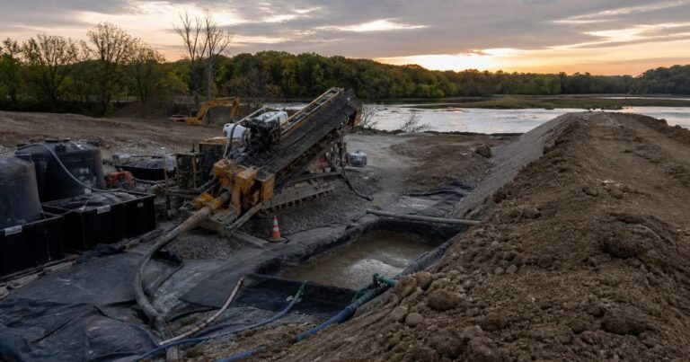
Frac-out prevention on an HDD project is a programme, not a single control: a bore plan that keeps annular pressure under the fracture gradient, a fluid programme built to measured targets, real-time pressure and pit-volume monitoring, disciplined reaming, and a rehearsed inadvertent return plan. This guide sets out the controls we use, in the order a crew meets them, and names what to measure, the trigger value that should stop work, and who acts.
What Does Frac-Out Prevention Require on a Typical Crossing?
Frac-out prevention is mostly about keeping annular pressure below what the formation can hold. A frac-out, or inadvertent return, is a loss of drilling fluid to the surface away from the entry and exit points; it happens when downhole pressure exceeds the confining pressure the ground can resist, or when fluid reaches a fault or a loose seam. The boundary is set by a fracture gradient commonly estimated at about 0.7 to 1.0 psi per foot of overburden depth, and that figure is the ceiling for every decision that follows.
Prevention is a chain, and the weak links are practical: shallow cover under a road, fluid mixed too thick, a crew that outruns the mud. The programme runs through five control families – bore plan, fluid design, instrumentation, operating discipline and the prepared response – each verified in the field by a named measurement, not by inspection of intent.
| Control | What it prevents | How it is verified in the field |
|---|---|---|
| Depth of cover and staged bore profile | Shallow-ground frac-out near roads, ditches and watercourses | Entry and exit profiles checked against the design cover minimums on the survey sheets |
| Entry and exit angles held in the 8-15 degree band | Profile changes that concentrate stress in the formation | Plan and profile sheet compared with steering records each rod |
| Fluid unit weight kept in the 9-10 lb/gal band | Over-heavy fluid raising annular pressure | Mud balance reading logged on each tank and after treatment |
| Gel strength and fluid loss tested to API RP 13B-1 | Poor filter cake and fluid leaking into permeable ground | Written test sheet per shift, retained in the bore record |
| Marsh funnel viscosity inside the target band | Cuttings beds and weak hole cleaning | Marsh funnel reading at the hopper and at the returns line |
| Annular pressure from a pressure sub plotted against the modelled limit | Pressure that exceeds the confining or overburden pressure | Real-time screen reviewed by the driller and the supervisor |
| Pit-volume and returns accounting | Undetected fluid loss into the formation | Pit level and flow-out checked on every rod |
| Inadvertent return plan and on-site containment | Escalation and spread of a spill when loss occurs | Plan walk-through and containment check before the bore starts |
Bore-Plan Controls: How Do Cover Depth and Geometry Keep Annular Pressure Under the Limit in Shallow Cover Next to a Road?
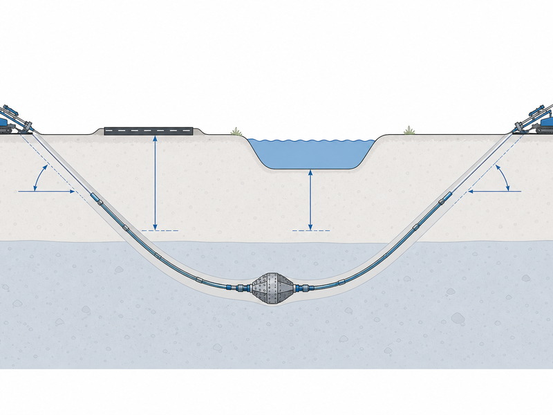
The cheapest frac-out prevention is designed before the rig arrives. Cover, angles, radius and profile decide how much overburden stands between the bore and the surface, and overburden is the confining pressure that keeps fluid in the hole.
- Depth of cover. Use as much as the corridor allows. Shallow cover under a road, ditch or watercourse is the classic frac-out location, because little overburden holds the fluid down.
- Entry and exit angles. These are typically designed in the 8-15 degree band, with design guidance often using about 8-12 degrees.
- Radius of curvature. Install only pipe that can bend within the designed radius, and keep the curve smooth; sudden profile changes create stress points.
- Staged depth. Reach design depth quickly, then run the bore flat. Long shallow sections keep the bore nearer the surface and nearer the annular pressure limit.
- Surface features. Route under sensitive features at full depth, and reduce the allowed downhole pressure where cover is thin.
In our bid reviews, the frac-out analysis is the document we re-check most often, because it links the geotechnical investigation to the bore profile and sets the allowable pressure at each station. The NASTT HDD Good Practices Guidelines and ASCE Manual of Practice 108 treat cover, radius and the frac-out analysis as design inputs, and our HDD crossing services and broader trenchless technologies are planned on that basis.
Fluid-Design Controls: How Do Mud Weight, Viscosity and Gel Strength Set the Margin I Need?
Drilling fluid holds the hole open, suspends and removes cuttings, cools and lubricates the tooling, and builds a low-permeability filter cake against the bore wall. Frac-out prevention depends on hitting the target rather than the extreme. Fluid that is too thin drops heavier cuttings into a bed and degrades return flow; fluid that is too thick raises annular pressure and can itself trigger an inadvertent return.
Density comes first. Drilling fluid unit weight is normally held between 9 and 10 lb/gal. HDD fluid commonly sits in the 30-60 second Marsh funnel band, and rheology, gel strength and fluid-loss testing are run to API RP 13B-1.
Gel strength holds cuttings in suspension when circulation pauses. Make-up water should be at pH 8-9 for additives to hydrate and mix properly; soda ash raises pH and stretches the additive. Additive selection belongs to our fluid-science page, but the field rule is simple: mix to a measured target and keep it there.
Hole cleaning and annular velocity are the quiet half of frac-out prevention. Fluid must move fast enough in the annulus to lift cuttings to the exit; if it cannot, the cuttings settle and the effective downhole pressure rises. In one equipment-maker worked example, a 300 ft bore with a 6 in reamer needs about 44 gal per 10 ft rod, and 1,320 gal for the crossing.
Using less fluid than the calculation requires makes the fluid too thick to move out of the pit and can end in an inadvertent return, ground heave or stuck tooling. The fix is to slow down or improve the fluid, never to push harder.
Applies to engineered water-based fluids. Prevention targets here assume a bentonite, PAC or PHPA system with controllable density, gel strength and fluid loss. Water-only suits short, small-diameter bores in stable, non-reactive ground and is not a prevention programme. When the fluid thickens, treat it with water or a deflocculant; adding more solids raises annular pressure and works against the margin.
Equipment and Instrumentation Controls: What Must Be Watched in Real Time as Pit Volume Starts Dropping?
How does frac-out prevention stay ahead of pressure and volume problems while there is still time to act? The central instrument is the pressure sub, which measures the downhole pressure and streams it to surface so the driller can plot it against the modelled allowable limit for the current station. The allowable pressure curve is built from the fracture gradient using a cavity-expansion method, whose dominant inputs are overburden depth and the friction angle of the overlying soil.
Pressure tells you how hard you are pushing; pit volume tells you whether fluid is going where it should. A returns-monitoring system compares fluid out against fluid pumped, so even a slow loss is visible rod by rod. Pressure climbing toward the limit is a warning, and a pit that will not hold level is a loss in progress.
- Pressure sub. Plot the pressure trace against the station-specific allowable curve; the trigger is a sustained approach to the limit, not one spike.
- Pit-volume monitoring. Compare returns with pump output on every rod; a falling pit or reduced flow-out is the trigger to slow down and investigate.
- Pump discipline. Track strokes and pump rate, and keep the pumps steady; unplanned stops let cuttings settle and let the fluid column sit against the formation.
- Fluid testing station. Keep the mud balance and Marsh funnel in use so fluid properties are known rather than assumed.
Name the division of responsibility before the bore starts: the driller acts on an excursion, the supervisor confirms the reading and decides whether work stops, and the fluid hand treats the mud and records each test. Our field teams record downhole pressure against the allowable curve for the full crossing, which turns a good or bad day into an auditable data set. Where independent confirmation is needed, a pipeline inspection service can add third-party verification.
Calibrate the thresholds before the bore starts, not during it. The allowable pressure curve comes from the frac-out analysis for that alignment; the mud-weight and Marsh funnel targets come from the soil log and hole size; the pit-volume baseline is established over the opening rods. Record who sets each number and who may change it.
Operating Controls: How Do Reaming and Pullback Discipline Prevent an Inadvertent Return on a Sensitive Crossing?
How does the crew protect the margin once the bore is designed and the fluid is mixed? Keep circulation and the bore’s relief path working: hold the pumps steady, keep annular velocity high enough to move cuttings, and never leave a loaded hole standing while the crew debates the reading.
- Controlled reaming-pass sizes. Size the reamer to the product: about 1.5 x outside diameter up to 9 in and about 1.3 x at 10 in and above, with good practice often quoted at 1.2-1.5 x. Too few or too large steps overload the annulus and spike downhole pressure.
- Controlled rates. Match reaming rate to fluid volume per rod against pump output; the constraint is usually fluid, not the rig.
- Stop to restore returns. If returns fall, slow the pump and stop advancing until circulation is re-established. Continuing to drill while returns are lost is how a small loss becomes a surface event.
- Treat the fluid, do not load the hole. When the fluid thickens, treat it with water or a deflocculant rather than adding more solids.
- Pullback discipline. Pullback speed is typically on the order of 1-3 m/min, governed by pipe-stress limits, buoyancy control and pump output.
- EPC engineer writing the inadvertent return plan: the plan needs named thresholds and named decision-makers, not only response actions.
- Supervisor on a shallow road crossing: the governing station is where cover is thinnest, and the trigger is a sustained approach to the curve, not a single spike.
- Owner’s representative reviewing a contractor method statement: check that the pressure curve, the fluid targets and the restart criteria appear as numbers, and that each has an owner.
Our pipeline installation services are planned so the string can be pulled within the stress and coverage limits the frac-out analysis assumed.
What Is the Prepared Response When Returns Are Lost?
No frac-out prevention programme is complete without a response rehearsed before it is needed. Under FERC-regulated projects and comparable regimes, the applicant submits an HDD plan and an inadvertent return plan covering monitoring, immediate response, containment and notification, and continuous examination of drilling-fluid pressures and return flows is a standard permit condition. A workable response has five parts: a defined stop-and-notify decision, containment ready on site, a cleanup method matched to the site, a clear restart gate, and a record of what happened. Set the stop-and-notify decision by trigger in advance.
An inadvertent return response stays credible on two habits: walking the plan on site before the bore starts, and treating every event as data. Where an inadvertent return reaches a watercourse or a sensitive area, specialist support can be brought in, and our emergency response and contingency maintenance team plans for exactly that case.
| Symptom observed | Immediate action | Restart criteria |
|---|---|---|
| Pit volume falls and returns are lower than pump output | Slow the pump, stop advancing, check for a surface seep and confirm the loss location | Full returns restored for at least two consecutive rods with a steady pit level and pressure below the limit |
| Pressure climbing toward the allowable curve | Reduce pump rate and penetration rate, circulate until pressure falls | Pressure holds below the limit at the target rate for a full rod |
| Surface seep, sheen or ground heave | Stop pumping, install containment, collect released fluid and notify owner and regulator | Written clearance after plan review and the cause is understood and controlled |
| Rising torque with declining returns (cuttings bed) | Stop pullback, run a hole-cleaning pass and treat the fluid | Clean returns and stable torque before resuming |
| Fluid thickening in the pit | Treat the fluid with water or a deflocculant; do not add more solids | Marsh funnel and gel strength back inside the target band |
Frequently Asked Questions
What is the most common cause of a frac-out on an HDD crossing?
Excess annular pressure in shallow cover is the most common cause. Prevention therefore works the shallow sections hardest: hold the pressure under the allowable curve, keep the fluid on target and watch pit volume every rod. Loose or coarse material, faults and weathered rock make it easier still.
How is the allowable annular pressure limit set for each station?
The limit comes from the fracture gradient, commonly estimated at 0.7 to 1.0 psi per foot of overburden depth. That value is converted into an allowable annular pressure curve for the bore path; on any crossing the governing limit is the one set at the shallowest station.
How often should I test the drilling fluid properties, and after what events?
At least once per tank or per shift, and again after any treatment. Mud weight, Marsh funnel viscosity, gel strength and fluid loss are the core checks, run to API RP 13B-1. Testing at the mixing hopper and at the returns line catches a fluid that is drifting before it reaches the hole.
Can frac-out prevention be run on water alone for most crossings?
Water alone is not a frac-out prevention programme on most crossings. Water cannot build the filter cake or carry heavy cuttings the way an engineered fluid does, and it offers no control over gel strength or fluid loss. It can be adequate only in short, small-diameter bores in stable, non-reactive ground.
What should a crew do the moment returns are lost?
Stop advancing, slow or stop the pump, and check for a surface seep. Slowing the pump lowers the pressure that is driving fluid into the formation, and lifting the fluid helps it carry cuttings while circulation is restored. The crew then follows the inadvertent return plan: contain, notify and do not restart until the restart criteria are met.
Does a pressure sub remove the need for pit-volume monitoring on its own?
No. Pressure and pit volume answer different questions. The pressure sub shows how much annular pressure is acting at the tool, while pit volume shows whether fluid is leaving the system into the ground. Either instrument can miss a loss on its own, so good practice runs both.
Key Takeaways
- Prevention starts with the design: cover depth, entry and exit angles in the 8-15 degree band and a smooth radius of curvature set the pressure margin.
- Keep the fluid on target: unit weight in the 9-10 lb/gal band, Marsh funnel viscosity inside the target range, and gel strength tested to API RP 13B-1.
- Watch pressure and pit volume together, and match reaming and pullback to the fluid the pumps can deliver.
- Treat the fluid rather than adding more solids, rehearse the inadvertent return plan, and set the restart decision by trigger in advance.
How JSW Supports Frac-Out Prevention on HDD Crossings
JSW is a pipeline engineering and construction company that executes trenchless crossings with its own crews and equipment. Our scope covers HDD crossing services, related trenchless technologies, usługi w zakresie montażu rurociągów, pipeline inspection service and emergency response and contingency maintenance.
We plan crossings with the frac-out analysis as a working document, and we log downhole pressure, fluid properties and pit volume as an auditable record. Pricing is risk-explicit, and safety and compliance are conditions of work.
- One team, one contract: engineering, drilling, installation and response under one accountable team.
- Records kept per crossing: pressure, fluid and volume records retained for the crossing.
- The governing case is priced: the governing case is priced rather than the average day.
- Response plans rehearsed: inadvertent return plans rehearsed on site before the bore starts.
Planning a crossing and need a prevention programme that holds up on site? Send your bore profile, geotechnical summary and target diameters for a free technical review. Our engineers respond with a scoped recommendation and budget range.





































 English
  Arabic
  Russian
  Spanish
  French
  Vietnamese
  Polish
  Thai
Thai  Indonesian
  Turkish
  Portuguese