
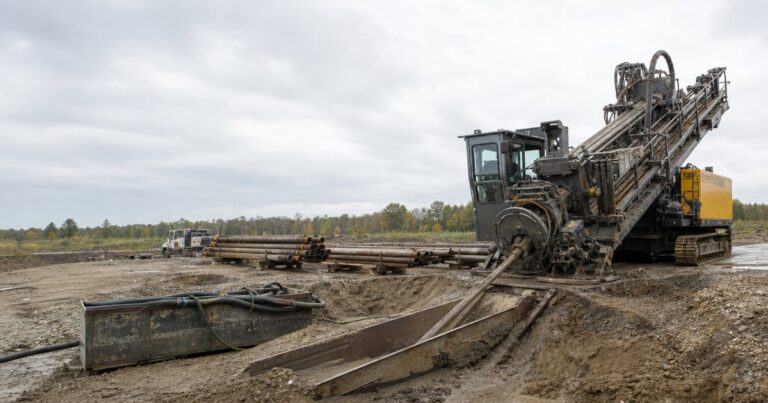
HDD rig selection (horizontal directional drilling) works from the jobsite backwards: build the load case first, convert it into the capability the crossing demands, then match a machine to it. That order matters, because two crossings of the same length can demand very different machines once pipe weight, geology, cover and access are taken into account.
This HDD rig selection guide follows the three steps we use in practice – build the load case, convert it into required capability, match the machine to it. It then gives a jobsite-archetype table, the package around the rig that is often forgotten, and the six most common selection errors. It closes with a short method an owner can use to sanity-check a subcontractor’s proposed rig.
Scope: this sequence applies to crossings whose ground can be characterised by interval and whose load case can be calculated. Where the bore is deep rock or the alignment runs under live infrastructure, the same load case applies but the guidance and tooling assumptions change first.
Which Comes First in HDD Rig Selection: the Jobsite or the Machine?
Most selection mistakes begin with a machine in mind. A contractor owns a rig, or has seen one work well on another project, and the crossing is then described in a way that fits it. Working from the ground up removes that bias and often produces a smaller machine.
The reason is that the machine is only a means of delivering force, torque, fluid and rods to the bore. The jobsite decides how much of each is required. A 1,200 ft crossing under a river with a 24 in steel product pipe differs from the same crossing under farmland. The geology, depth of cover, entry geometry and access are all different.
- The load case comes from the site and the pipe. It is assembled from site and pipe data before any machine is considered.
- Required capability is the translation. The load case is converted into numbers a machine can be judged against.
- The machine match is the supply side. Only now do a specific rig, its drill pipe and its support equipment enter the discussion.
In our equipment reviews we see this sequence applied well on transmission main crossings and skipped on short utility bores. Short utility bores are where the load case is most often skipped, and skipping it is the single most common source of late changes on small crossings.
Step 1: Build the Load Case From the Jobsite
Step 1 builds the load case – the demand side of the problem – as a short, structured list of the conditions the crossing has to beat. Gather it before you talk about machines, because every later step in HDD rig selection depends on it.
- Product pipe: outside diameter, wall thickness or dimension ratio (DR), material, weight per foot, and whether it is steel, HDPE or a carrier pipe inside casing.
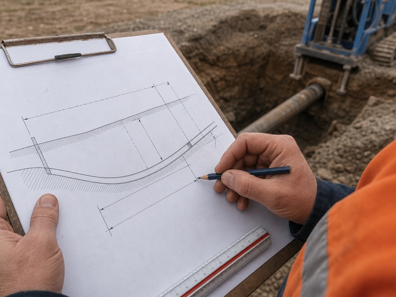
- Bore length and depth of cover: the drilled length and the minimum cover over the product pipe, which together set the profile and the required bend radius.
- Entry and exit geometry: the entry and exit angles and the setback distance available on each side.
- Geology by interval: soil and rock type along the alignment, not just at the entry pit, with the interval over which each condition holds.
- Access and footprint: pit sizes, working width, crane reach and whether the site is urban or remote.
- Permitting window and fluid disposal: the time allowed on site and how drilling fluid and spoil will be handled and removed.
Each item pushes the machine in a specific direction. Pipe weight and bore length drive pull load; depth of cover and product stiffness drive the profile and therefore torque. Geology drives tooling, torque and fluid, while access and permitting drive how much support equipment and working hours are needed.
| Load-case input | What it changes | Machine-side consequence |
|---|---|---|
| Product pipe OD, DR and weight | Required pull and thrust, and the size of the final reamed hole | Minimum pullback force, reamer size and pipe-handling capacity |
| Bore length and depth of cover | Profile length, bend radius and fluid volume | Rod length and count, pump volume, torque reserve |
| Entry and exit angles and setback | Feasible profile and pit layout | Rig footprint, entry angle range and vise position |
| Geology by interval | Tooling family, torque and cuttings load | Torque rating, pump flow and drill string strength |
| Site access and footprint | Machine size that can be brought in and set up | Transport weight, working width and crane capacity |
| Permitting window and fluid disposal | Working hours and support equipment | Ancillary package: mixing, recycling and tanking |
Step 2: Convert the Load Case Into Required Capability
Step 2 turns site data into machine requirements using the 2026 practice we apply. Four numbers matter most, and each is calculated rather than assumed.
- Calculated pull load with margin. The pull load comes from pipe weight, friction, drag, buoyancy and the bend and reaming loads along the profile, carried with margin.
- Required torque. Torque has to turn the reamer and drill string through the ground being crossed, and mixed or hard ground raises it sharply.
- Required fluid volume and flow. Drilling fluid must carry cuttings out of the hole and stabilise the bore; too little flow leaves cuttings downhole and raises the risk of a stuck string.
- Rod diameter and drill string strength, and backreaming thrust. The drill pipe has to carry the torque and tension, and the rig has to push the reamer forward as well as pull it back.
Pull load sets the minimum machine class, and it is the one most often under-calculated. Equipment and tooling choices are inputs to project-specific design and must be confirmed by a competent engineer for the actual crossing. A machine’s rated maximum pullback is never a design limit. Pull load calculations are commonly carried with a safety margin of about 1.5-2.0, so the rated figure has to sit well above the calculated load, not at it.
Our field teams record the calculated pull load, the torque used and the mud volume on every crossing, which shows whether the machine was matched or simply large enough. When torque runs near a machine’s limit for most of a reaming pass, the match is wrong even if the pipe comes out.
Step 3: Match Required Capability to the Machine
With the numbers in hand, the final stage becomes a comparison rather than a guess. Each requirement maps to a specific machine parameter, from pullback force and torque to the drill pipe the profile can accept. The product pipe string itself still has to be handled and installed, which is where serviços de instalação de condutas begin.
- Pullback force against the calculated pull load plus margin.
- Torque against the highest torque demanded by the hardest interval.
- Pump capacity and pressure against the required fluid volume and flow for cuttings transport.
- Rod size and drill pipe strength against the torque, tension and bend radius of the profile.
- Vise and pipe handling against the rod sizes used and the make-and-break time allowed.
- Footprint and transport weight against the access, pit size and road limits.
- Ancillary package against fluid handling, guidance and lifting needs.
We have seen a rig rejected on paper for pulling capacity when the real constraint was transport weight into a congested downtown pit. A smaller machine with a better support package completed the crossing. On that crossing the transport weight into a congested downtown pit, not the rig’s rated pullback, decided which machine could be used.
Which Rig Fits an Urban Bore, a River Crossing or a Rock Ridge?
Most crossings fall into a few recognizable types. The table below pairs each archetype with the capability it drives and the trap that catches crews most often. The archetype table is a starting point only; the load case for the actual crossing always governs, and where another method fits better, the available trenchless technologies come first.
| Jobsite archetype | Capability driver | Typical trap |
|---|---|---|
| Urban utility bore (short, shallow) | Small rig with fast setup, compact footprint, shallow walkover-friendly depth | Choosing by pipe diameter alone and ignoring existing utilities and clearance |
| River crossing | High pullback, large mud volume, long rod string, heavy reaming thrust | Under-estimating pull load from buoyancy and length, then running short of fluid capacity |
| Highway or rail crossing | Accurate profile, cover below the asset, tight permitting window | Squeezing the profile to shorten the bore and breaking the required bend radius |
| Deep long crossing | Torque reserve, drill string strength, downhole guidance without surface access | Assuming a walkover locator will reach the depth the profile actually needs |
| Rock ridge | High torque, rock tooling, a mud motor (a downhole motor driven by the drilling fluid), robust fluid handling | Matching pullback but ignoring torque and tooling, then stalling on the ream |
| Large-diameter transmission | Very high pullback and thrust, staged reaming, heavy pipe handling | Designing to a rated maximum pullback instead of a calculated load with margin |
| Congested downtown | Compact footprint and transport weight, low noise, tight fluid containment | Specifying a rig that fits the bore but not the street or the working hours |
Two archetypes can look identical on a plan and still demand different machines. A highway crossing in open farmland tolerates a steeper setup and a simpler fluid plan, while the same crossing at a city interchange brings traffic control, noise limits and containment.
What Ancillary Equipment Decides Whether the Rig Can Actually Work?
A matched rig with a weak support package still fails. The ancillary package is where several jobs are won or lost, and it is routinely the last thing specified.
- Mud mixing and recycling: mixing capacity, shear time and solids control set the drilling fluid volume available per hour and the spoil that leaves site. On long or large-diameter bores the recycling plant, not the rig, limits progress.
- Tracking and guidance: walkover locators for shallow work, where a hand-held receiver reads a sonde signal from the surface. Downhole magnetic or gyro systems take over where cover is deep, steel casing is present or surface access is blocked.
- Cranes and pipe handling: lifting capacity and reach for pipe strings, reamers and the drill string, plus a handling method that keeps crews safe at both pits.
- Pullback hardware: pulling eyes, swivels and adapters. The swivel isolates rotation from the product pipe, and the load; misalignment puts side load on the connection instead of a clean pull and can stretch the product pipe.

On crossings we have supported, the reaming plan, the drilling fluid recycling plant and the pullback head decided how a pullback ran more often than the rig’s tonnage did. Threaded pullback connections are reliable but slow to make and break, which matters most in tight urban pits and during multi-stage reaming.
Six Costly HDD Rig Selection Errors
The same mistakes recur across project classes. Naming them makes them easier to catch at proposal stage.
- Selecting from pipe diameter alone. Diameter says nothing about length, geology, cover or access, so it cannot set the machine class by itself.
- Designing to the rated maximum pullback. A rated figure is a limit, not a working value; the calculated pull load with a margin of about 1.5-2.0 governs.
- Ignoring torque and fluid. A rig with enough pullback force but too little torque or pump flow will stall on the ream or leave cuttings downhole.
- Treating geology as one material. A single rock or abrasive interval can force rock tooling, extra torque and a different fluid plan for that section alone.
- Counting tonnage and forgetting logistics. Transport weight, footprint, road limits and working hours can rule out a machine that is technically capable.
- Leaving the ancillary package to the field. Fluid, guidance, lifting and pullback hardware decided late are the most common cause of avoidable downtime.
How an Owner Can Sanity-Check a Subcontractor’s Proposed Rig
An owner does not need to redo the design to ask good questions; the goal is to confirm the proposed machine was chosen from the calculated load, not from availability.
Ask for the calculated pull load, the margin applied, and the torque and fluid figures behind the proposal. Then compare those numbers with the machine’s ratings, and walk through access and transport. A sound answer is specific and traceable to the crossing; a weak one repeats the machine’s specifications. Where the completed line has to be verified after installation, an independent pipeline inspection service records the as-built against the permit tolerance.
| Question to ask | What a sound answer looks like | Red flag |
|---|---|---|
| What is the calculated pull load and margin? | A figure from the site and pipe data with the margin and assumptions stated | Only the rig’s rated pullback force is quoted |
| What is the highest torque the profile demands? | Torque tied to the hardest interval, with reserve against the machine | Torque is not mentioned at all |
| What mud volume and flow are required? | A volume and flow rate with a solids-control plan | Pump size quoted with no volume calculation |
| Does the rig fit the site and the road limits? | Footprint, transport weight and setup time checked against access | Access treated as the contractor’s problem |
| Which guidance system suits the depth and cover? | A system chosen for the depth, interference and surface access | Walkover assumed for a deep crossing |
| What is in the ancillary package? | Recycling, lifting, pullback hardware and spares named | Support equipment left to be decided on site |
A useful check is to ask what would change the machine choice. If nothing would – not a longer bore, harder rock or a tighter site – the proposal was not built from the site data. Owners who ask early get a more honest scope and a better-priced bid.
Frequently Asked Questions
What is the most important factor in HDD rig selection?
The calculated pull load with a safety margin is the factor that sets the minimum machine class. It combines pipe weight, friction, drag, buoyancy and the bend and reaming loads, and everything else is checked against it.
How much margin should I allow above the calculated pull load?
A safety margin of about 1.5-2.0 on the calculated pull load is common in practice. The margin covers the uncertainty in the site and pipe data, so a machine’s rated maximum pullback is never used as the design value.
Can one HDD rig cover every jobsite archetype?
No, because the archetypes drive different capabilities. A compact machine suits short urban utility bores, while river crossings and large-diameter transmission work demand high pullback, torque and fluid volume that a small rig cannot provide.
How does geology by interval change the machine match?
A single hard or abrasive interval can set the torque, tooling and fluid requirements for the whole bore. Matching the easiest ground and ignoring the interval that needs the most torque is a common cause of stalling on the ream.
What ancillary equipment is often forgotten in HDD rig selection?
Mud mixing and recycling, tracking and guidance, cranes and pipe handling, and pullback hardware are the items most often left until late. Any of them can limit progress even when the rig itself is correctly matched.
How can an owner check a subcontractor’s proposed rig?
Ask for the calculated pull load, margin, torque and fluid figures, then compare them with the machine’s ratings. A proposal that traces those numbers back to the crossing is far more reliable than one that only quotes the rig’s specifications.
I need to cross 1,200 ft under a river with a 24 in steel pipe – what size HDD rig do I need?
The pipe diameter does not set the machine class; the calculated pull load with its margin does. Pipe weight, bore length and the ground along the alignment set the pull load, and the rated pullback force then has to sit well above that figure with a margin of about 1.5-2.0. Torque and fluid volume follow the same logic, so the answer is a capability set rather than a single machine size.
Key Takeaways
- Build the demand side from the jobsite first: pipe, length, cover, geometry, geology, access and permitting.
- Convert it into required pull load with margin, torque, mud volume and drill string strength before naming a machine.
- Match machine parameters to those requirements, and treat the ancillary package as part of the rig, not an afterthought.
- Never design to a rated maximum pullback; carry the pull load with a margin of about 1.5-2.0.
- Use the jobsite archetype only as a starting point, then confirm against the site and pipe data for the crossing.
- Owners can verify a proposal by asking for the load figures, not by comparing tonnage alone.
How JSW Supports HDD Rig Selection and Crossings
JSW executes trenchless crossings with its own crews and equipment. Our scope covers HDD crossing services e microtunneling construction.
We match equipment to the load case rather than to the fleet, keep design and process data auditable, and price risk explicitly. Crossings are planned by engineers accountable for the build.
- Integrated delivery: engineering, equipment and crews under one scope, so the rig, tooling and package are chosen together.
- Auditable design and process data: load cases, pull loads and fluid figures recorded and traceable.
- Risk-explicit pricing: site, geology and access risks identified and priced openly.
- Safety and compliance: work planned to recognised pipeline and trenchless standards.
Want your HDD rig selection checked against the actual crossing? Send your pipe data, bore length, profile and survey information for a free technical review. Our engineers respond with a scoped recommendation and budget range.





































 English
  Arabic
  Russian
  Spanish
  French
  Vietnamese
  Polish
  Thai
Thai  Indonesian
  Turkish
  Portuguese