
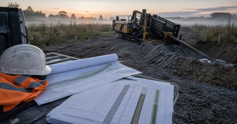
HDD limitations (horizontal directional drilling limitations) are the conditional envelopes that decide how far, how large and through what ground a crossing can be drilled. Ground conditions, length, geometry, guidance accuracy, product-pipe stress and site logistics each set one envelope, and the practical limit on a crossing is whichever envelope closes first. This catalogue quantifies each limit as a mechanism, a mitigation and a residual risk, then lists the counter-indications where HDD should not be attempted. Every figure here is a planning input and must be confirmed by a competent engineer for the actual crossing.
What Are the Main HDD Limitations for Pipeline Crossings?
Reading these as hard stops is as misleading as reading them as soft preferences, because most behave as gradients. The table below answers the core question directly, listing each system limit as a mechanism, a mitigation and the residual risk that survives it. Ground-related limits follow in the geological section; both tables screen options and do not replace project-specific calculation.
Residual risk is stated relative to design and price: Low is closed by standard design; Moderate changes the fluid plan or the contingency; Moderate to high usually changes both; High can change the method or the route.
| Limit | Mechanism | Mitigation | Residual risk |
|---|---|---|---|
| Crossing length against rig capacity | Friction, fluid drag and curvature effects accumulate along the bore | Larger machine, staged reaming, buoyancy and weight control | Moderate; load estimates stay soil dependent |
| Diameter and reamed hole size | A larger reamed hole raises torque, fluid demand and the number of passes | Staged reaming, bigger fluid system, torque monitoring | Moderate; hole instability in coarse soil |
| Inadvertent return and frac-out | Fluid escapes along fractures or through shallow cover | Containment, pressure and rate control, added cover | Moderate; some pathways stay unmapped |
| Bend radius and entry or exit angle | Curvature drives pipe stress and limits how tightly the path can turn | Longer setback, lower angle, calculated stress checks | Moderate; the site may not allow the extra room |
| Guidance accuracy with depth | Positioning signals weaken and errors accumulate along the bore | Wireline or gyroscopic steering, more frequent surveys | Moderate; tolerance must absorb deviation |
| Product-pipe stiffness and buckling | Wall thickness and dimension ratio limit curvature and compression | Thicker wall, buoyancy control, controlled pull speed | Moderate to high |
| Site footprint and rig class | The machine, pits and pipe string need space and access | Rig class selection and temporary works | Moderate; land and access may not be available |
The rows are not independent: enlarging the reamed hole to transport cuttings also raises torque and fluid demand, and lowering the entry angle to ease pipe stress lengthens the setback. In our design reviews, crossings are rarely stopped by one limit alone; they are stopped by two that each looked acceptable in isolation. The practical method is to list every limit that applies, close each one in turn, and find which two close first; that pair fixes the design, the contingency and the price before geometry is frozen.
Length and Diameter Limits: How Far and How Large Can a Crossing Be?
The achievable length of an HDD crossing is governed mainly by pullback load and by how well the drilled hole can be cleaned over the whole run, which depend on the rig, the ground and the pipe. Friction, fluid drag and the capstan effect around curves accumulate along the bore, so load grows faster than length. Published machinery ranges span roughly 3.6 t to 617 t of pullback across the recognised classes; one planning document calls maxi rigs those above 100 t, while a UK consent submission places midi rigs at roughly 15 to 40 t of pullback and 15 to 30 kN.m of torque. Because class boundaries differ between organisations, the useful exercise is to match a calculated pullback load, with margin, to a specific machine. In our experience, the length limit is reached through fluid and torque management before the rig runs out of pullback capacity.
NASTT good practice places the reamed hole at about 1.2 to 1.5 times the product pipe outside diameter, and a larger hole demands more torque, more fluid and more reaming passes.
A documented scale reference is the Yangtze River crossing on the Jiangdu-Rudong gas pipeline in 2016: twin 711 mm pipes over 3,300 m; it is a record, not a target, and relied on capability that cannot be assumed elsewhere.
Length and diameter are the pair of HDD limitations most often quoted and least often quantified, because neither can be stated without naming the rig and the soil.
Geological Limits: Which Ground Conditions Rule Out a Bore?
Ground conditions, and how the ground behaves while it is cut, steered and reamed, decide more crossings than any other single factor; hardness alone does not describe the problem.
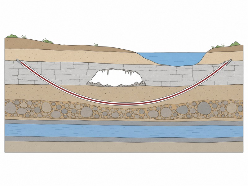
The table below sets out each ground-related limit, how it constrains the bore, the typical mitigation and the residual risk.
| Ground condition | How it limits the bore | Typical mitigation | Residual risk |
|---|---|---|---|
| Massive or very high strength rock | Penetration is slow and tooling wears quickly | Correct bit and downhole motor, staged reaming | High; low rate of advance and tool wear |
| Rock head at shallow cover | Cover cannot be gained or held above the bore | Re-route, or add cover where the profile allows | High |
| Cobbles and boulders | The hole will not stay open and the head deflects | Shorter bore, casing, or another method | High |
| Karst and solution voids | Fluid disappears into openings that are not mapped | Grouting, casing, or avoidance | High |
| Glacial till with embedded boulders | Hard and soft material alternate unpredictably | Matched tooling and a slower advance | Moderate to high |
| Clean sand and gravel | Fluid loss and poor hole stability | Managed fluid properties and adequate cover | Moderate |
| High artesian head | Inflow, fluid dilution and a blow-out drive | Controlled fluid density and a blow-out plan | Moderate |
| Fractured and fissured rock | Fluid follows fractures toward the surface | Pressure and rate control with monitoring | Moderate |
Artesian flow and karst both produce fluid that leaves the bore where nobody planned it to, and both are easier to manage when the geotechnical profile identifies them before drilling starts. We have seen crossings judged feasible on a single rock-strength value that then struggled because the ground between the boreholes was more variable than the samples suggested.
Inadvertent Return and Drilling Fluid Loss: How This Limit Is Reduced, Monitored and Priced
Inadvertent return (commonly called frac-out) is drilling fluid reaching the surface outside the entry and exit pits. It is the limit with the least certainty, because the pathways that carry fluid are seldom mapped in advance.
The mechanism is pressure driven. When bore pressure exceeds the resistance of the ground and cover above the bore, fluid finds a path to the surface.
Managed fluid density and viscosity, a controlled advance rate, adequate cover, containment and monitoring along the alignment all lower the probability and limit the consequences. A response plan must be ready before the pilot hole starts, with disposal and recycling capacity sized for a loss event rather than a routine day.
Frac-out already has dedicated coverage on this site, so this catalogue only positions it: inadvertent return is one of the HDD limitations that can be reduced, monitored and priced, but not designed away entirely.
Geometry and Guidance Limits: What Sets Bend Radius, Entry Angle and Depth?
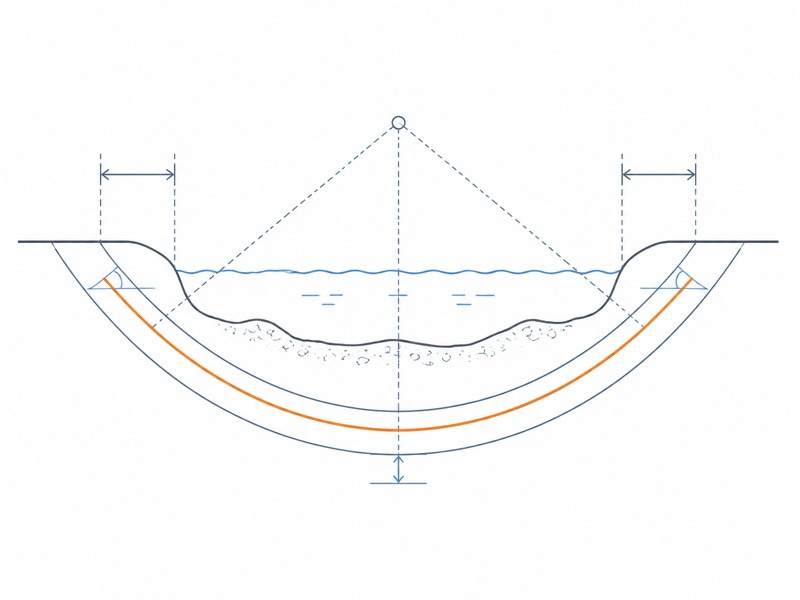
Entry and exit angles are commonly quoted in the 8° to 18° band, governed by rig capability and by how quickly depth must be gained to hold cover. A steeper angle reaches depth sooner but tightens the curvature at each end.
Bend radius is the practical expression of that curvature. Rules of thumb, which are planning aids rather than design values, put drill pipe at roughly 100 to 200 ft of radius for every inch of pipe diameter, and HDPE product pipe at about 25 to 35 times its outside diameter. A published planning rule of thumb for the directionally straight setback is 5:1, meaning five units of horizontal setback for each unit of depth, derived from the effective bend radius of the drill pipe or the product pipe.
Depth sits under the same constraint. Achievable depth is not purely a drilling question: it is bounded by guidance accuracy, by the length of approach needed to reach it, and by the space available at each end. Cover for buried crossings is commonly specified between 0.9 and 1.5 m, with reviewed HDD projects averaging a cover-to-diameter ratio of about 1.5. Under a watercourse, cover is set by scour and channel-bed stability rather than by a fixed figure.
Guidance accuracy falls as depth increases. Walkover surface locating works only near the surface, and the working depth quoted in industry material varies with soil, interference and transmitter power. Deeper bores generally need wireline or gyroscopic steering that surveys at intervals rather than continuously. Each system carries its own accuracy budget, and as-built deviation in long bores is normal rather than exceptional, so tie-in tolerances must absorb it. This is where several HDD limitations meet at once, and it is usually the end areas, not the geology, that decide the final geometry.
How Do the Product Pipe, Rig Class and Site Limit a Crossing?
A crossing can be drillable and still fail on the product pipe or on the site, where dimension ratio, wall thickness and working-area footprint set limits as decisive as the ground.
Product pipe: DR, wall thickness and deflection
Dimension ratio, wall thickness and allowable deflection govern how tight a curve the pipe can follow and how much it can deform during installation. ASTM F1962 is the usual framework for maxi-HDD placement of polyethylene pipe and conduit under obstacles including river crossings. Its editions in force at the time of writing are F1962-22 and the more recent F1962-25, and a revision work item (WK93768) proposes an 8% deflection limit across all DR ratings for both pressurised and non-pressurised pipe; the edition should be confirmed before a design is frozen. ASCE Manual of Practice 108, Pipeline Design for Installation by Horizontal Directional Drilling, is the usual companion on the pipeline-design side.
Can the Pipe Buckle or Collapse During Pullback?
Thin-wall, large-diameter pipe is the most exposed. Pullback applies axial tension; backreaming and any pushing apply compression, where buckling can become the controlling case; net external pressure during installation can govern collapse. Buoyancy control, whether by filling the pipe or adding weight, changes the load path and therefore the pullback load the rig must deliver. These checks are calculated for the specific pipe and crossing, not selected from a table.
Rig Class and Site Footprint Decide What Is Buildable
Rig class follows from the calculated load and from the site, and class boundaries are not identical across organisations. A larger machine needs more room, transport and fluid capacity, so a rig that is capable on paper can still be excluded by the entry and exit areas, the access roads, or the length of pipe string that must be laid out, welded and coated before pullback.
How Schedule, Weather and Fluid Disposal Add to the Limits
Schedule, weather and fluid disposal add three practical limits that can move method selection as decisively as any geological one. A long crossing must be drilled in a single continuous operation, and a part-finished bore cannot be left with tooling in it for days. Weather affects watercourse crossings through flood stage, current and access.
Fluid disposal is a logistics limit in its own right: drilling fluid and the cuttings it carries must be contained, recycled or disposed of lawfully, and that capacity must exist on site before the bore begins. Each of the three is closed through planning and logistics rather than through the ground, which is why these HDD limitations are priced early.
Counter-Indications: When HDD Should Not Be Attempted
Eight conditions are near-stops rather than gradients, and recognising them early is cheaper than discovering them on site.
- Shallow rock with thin cover. The bore cannot gain enough cover to ream safely, and rock reams slowly.
- Cobble or boulder zones with no fine-grained layer. The hole will not stay open and steering is unpredictable.
- Karst or open void systems that cannot be grouted. Fluid loss is probable and the bore may not track through the void.
- High artesian flow that cannot be controlled. Inflow and blow-out risk are difficult to contain.
- A product pipe too stiff for any available bend radius. The pipe cannot follow the bore without exceeding allowable stress.
- Crossings so short and shallow that open cut or another trenchless method is clearly cheaper and lower risk.
- Entry or exit areas too small for the rig, the pipe string or fluid containment.
- Fractured rock with unmapped pathways and no acceptable tolerance for frac-out.
None of these is an absolute prohibition, but they are the cases where a project should expect a strong reason to proceed rather than a weak reason to try. On crossings we have supported, the least expensive decision has sometimes been to step back from HDD before mobilisation rather than re-engineer a bore during construction.
These stopping conditions feed two other decisions in this series: the feasibility questions in our HDD feasibility and design guide, and the method-selection view in our guide to when HDD is the right choice. Where two or more apply, price the alternatives before geometry is fixed; where the crossing survives, these limits are carried into the drawing set as set out in our HDD bore plan guide.
Frequently Asked Questions
What are the main limitations of HDD?
The main limits are ground conditions, length and diameter, geometry, guidance accuracy, product-pipe stress and site logistics. Each sets a conditional envelope, and the practical limit on a crossing is whichever envelope closes first.
What is the maximum length HDD can achieve?
There is no fixed maximum length for HDD. The practical limit is set by pullback load and by how well the hole can be cleaned over the whole run, both of which depend on the rig, the ground and the pipe rather than on length alone.
Can HDD be used in rock?
Rock can be drilled; its limits depend on strength, abrasivity and fracturing rather than on the presence of rock alone. Massive rock slows penetration and wears tooling, while fractured rock risks fluid loss, so rock type and condition matter more than a simple rock or soil label.
What is inadvertent return, and why does it limit HDD?
Inadvertent return is drilling fluid that reaches the surface outside the entry and exit pits. It limits HDD because the pathways that carry fluid cannot be fully mapped in advance, so it can be reduced and monitored but not completely designed out.
At what depth does HDD guidance become difficult?
Guidance accuracy falls as depth increases. Published working depths differ widely between sources, so no single figure is reliable; as a typical range, walkover locating is commonly described as practical to roughly 9 to 12 m in favourable conditions, beyond which wireline or gyroscopic steering is used with periodic survey stops.
When should HDD not be used?
HDD should not be attempted where the limits cannot be met at acceptable risk or cost. Typical counter-indications include thin cover over shallow rock, ungroutable karst, uncontrolled artesian flow, cobble and boulder zones with no fine-grained layer, and a product pipe too stiff for any available bend radius.
Key Takeaways
- HDD limitations are conditional envelopes, not fixed values, and each one depends on site conditions and project requirements.
- Length and diameter are set by the rig class, the ground and the pipe together, so no universal maximum exists.
- Inadvertent return can be reduced, monitored and priced, but it cannot be fully designed out.
- Geometry and guidance limits interact: angle, cover, bend radius and setback move together, and accuracy falls with depth.
- Fluid disposal, weather windows and site footprint are constraints in their own right, and some crossings are genuine counter-indications for HDD.
How JSW Works Within HDD Limitations
JSW is a pipeline engineering and construction company that plans and executes crossings with its own engineering team, crews and equipment. Our scope covers HDD crossing services, trenchless technologies e microtunneling construction. It extends to pipeline cold bending e serviços de instalação de condutas, closing the practical limits early.
Because the same team prepares the crossing design and then builds it, our design basis reflects what the equipment and crews can actually achieve. We price risk items and their triggers explicitly rather than absorbing them into a lump sum, document the engineering basis behind each recommendation, and hand over the as-built records. Where the limits above point against HDD on a given crossing, we say so before mobilisation and propose an alternative instead of forcing a bore.
- Integrated delivery: survey interpretation, bore plan, stress checks, pipe string fabrication and pullback under one scope, which removes interface risk between designer and constructor.
- Constraint-first engineering: each crossing is tested against the limits in this catalogue before geometry is fixed, so the counter-indications surface early.
- Risk-explicit pricing: contingencies and their triggers are stated, not wrapped into a single figure.
- Auditable records: calculations, fluid plans and installation records are kept for construction review and later integrity management.
Not sure which limit governs your crossing? Send the crossing survey, the geotechnical profile, the pipe data and the working-area limits for a free technical review. Our engineers respond with a scoped recommendation, the pair of limits that closes first, and a budget range.





































 English
  Arabic
  Russian
  Spanish
  French
  Vietnamese
  Polish
  Thai
Thai  Indonesian
  Turkish
  Portuguese