
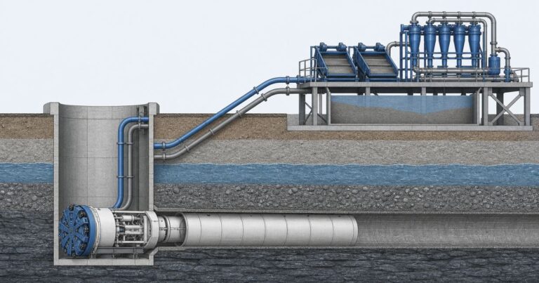
Slurry microtunneling – a microtunneling method in which a pressurized slurry holds the excavation face and carries the spoil back to the surface – lets a drive advance below the water table without dewatering the ground around it. Its defining control is face pressure: the support pressure held in the machine chamber, which balances the groundwater pressure and the lateral earth load at the face. The set point sits above the local groundwater pressure and below the level that heaves the ground, and it is re-set as the ground or the water table changes along the drive.
The balance that defines slurry microtunneling
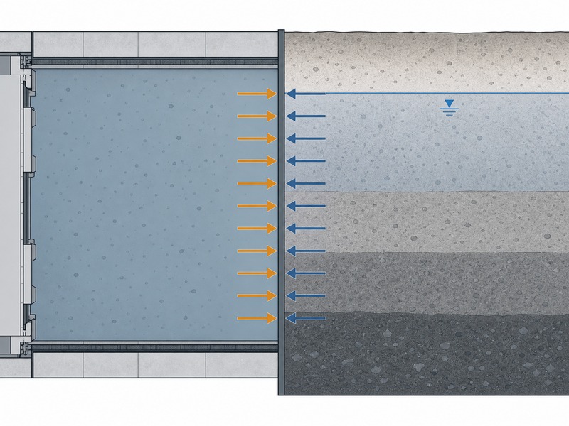
The face of a tunnel below the water table is a pressure boundary. On the ground side there is lateral earth pressure and groundwater pressure; on the machine side there is the support pressure held in the chamber. For the face to stay stable, the support pressure must be at least equal to the sum it is resisting, and it must never be so high that it lifts the ground above.
A slurry machine deals with this by providing earth pressure to balance the lateral earth loads and slurry pressure to balance the groundwater pressure. The support is therefore a controlled, measurable quantity, not an assumption, and it can be set and adjusted as the drive advances. A published water utility’s microtunneling and pipe jacking specification allows slurry microtunneling drives from about DN300 and individual drive lengths up to about 1 km, which makes the pressure balance a long-term control task rather than a one-off setting.
Because the balance is a pressure relationship, it is sensitive to depth, to ground density and to the water table. A drive that starts above the water table and then passes below it changes its support requirement without any change to the machine, so the pressure schedule has to follow the alignment rather than a single site reading. The same is true of a change in stratum: a face that is comfortable in a dense sand may need a different set point in a soft clay or a loose gravel immediately behind it. A municipal owner who has to accept the drive, an EPC bidder who has to price the slurry system, and a third-party design consultant who has to approve the pressure schedule all read the same balance, and all three need it stated per reach rather than for the site as a whole.
What the slurry does: support medium and transport medium
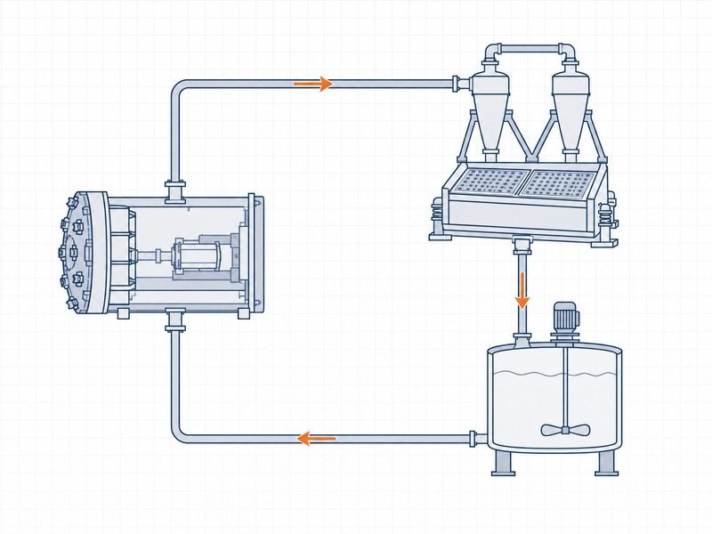
The slurry has two jobs at the same time. As a support medium it holds the face and forms a filter cake that limits seepage; as a transport medium it suspends the excavated material and carries it back to the surface. Neither role can be ignored, because a change made to improve one usually affects the other.
The transport role sets the minimum flow velocity in the return line. If the velocity is too low, the spoil drops out and the line can block; if it is too high, the extra energy wears the pumps and the pipework. In our design reviews we treat the slurry circuit – the feed and return lines between the machine and the surface – as a hydraulic system with a pressure budget, in the same way the machine itself is treated. A blocked or over-pressured line stops face support as surely as a machine fault, and the minimum flow velocity that keeps the spoil in suspension is part of that budget.
- Support: holds the face and forms a filter cake that limits water inflow.
- Transport: suspends and carries cuttings to the surface.
- Filtration: the cake is what allows pressure to be transmitted without excessive loss.
- Density: the primary lever for adjusting how the slurry behaves in the ground.
Formulating the slurry: bentonite slurry, clay-water and polymer
The base fluid is usually a bentonite slurry, a clay and water mix, or a polymer system. Bentonite is the classic choice because it builds viscosity and filtration control at low solids content, so the slurry can form a thin, low-permeability filter cake on the face while staying pumpable. A clay and water mix is used where the ground itself supplies suitable fines, and polymer systems are used where a lighter or more controllable fluid is preferred.
Formulation is not a fixed recipe. Density and filtration control are adjusted to the ground, and where the drive passes through open or fissured ground the density is increased deliberately to counter slurry loss and prevent face collapse. The separation plant must be able to make that adjustment, because density is the operator’s main tool for responding to a change in the ground.
The consequences of a poor formulation are predictable. A slurry that is too thin loses into permeable ground and the face loses support; a slurry that is too thick is hard to pump, hard to separate and slow to return. In our experience it is the filtration behavior, not the density alone, that decides whether the cake forms properly, which is why the daily tests matter more than a single design value.
Setting face pressure: the window between collapse and blow-out
If the question is whether a drive can be advanced under a river without dewatering – say a 400 m crossing with the face in loose sand – the answer is the pressure window: the set point sits above the local groundwater pressure with a margin that reflects the ground and the depth. The lower bound is the collapse limit, where further reduction lets the face lose ground and the surface settle. The upper bound is the level at which the support starts to lift the ground, which can heave the surface or drive the slurry along a weak path to the surface.
The set point is set at the start and then re-set as the drive advances, because the ground and the groundwater conditions change along the alignment. The adjustment is based on measured chamber pressure and on the excavated volume against theoretical volume rather than on a single predetermined figure.
One published shallow-drive case study reported an earth chamber pressure of about 153 kPa as the more reasonable value for face stability in that ground, against a most reasonable grouting pressure band of 600–700 kPa. The figure is specific to that project’s depth, cover and ground; it is not a design default. Write the set point per reach, with the depth, groundwater head and ground type each band depends on, and re-issue the schedule whenever the alignment crosses a stratum change; that is what makes the window auditable rather than a single figure carried across the drive.
| Condition | Risk if pressure is too low | Risk if pressure is too high |
|---|---|---|
| Soft or fine ground | Face loss and settlement | Heave and surface damage |
| Loose coarse ground | Ground runs into the face | Slurry escapes to the surface |
| Mixed face | Uneven support and deviation | Differential heave and over-excavation |
| Shallow cover | Trough forms above the pipe | Blow-out along a short path |
The table reads as a single window: the lower bound is the collapse limit and the upper bound is the heave or blow-out limit, and the operating set point is the value between them that the daily monitoring confirms.
The separation plant and density control
The plant is the part of the system that keeps the slurry usable. Returning slurry carries the spoil, and the plant removes it using screens for coarse material, cyclones for sands and, where the fines are difficult, a centrifuge. The cleaned slurry is then reconditioned and returned to the drive at the density the face requires.
A published water utility’s microtunneling and pipe jacking specification requires the separation plant to be able to increase slurry density to counter slurry loss and prevent face collapse, and expects a project to justify any proposal not to fit one. This is where control of the whole drive lives: if the plant cannot hold the density, the operator loses the main tool for responding to a change in ground, and the face pressure window narrows.
Slurry that is returned too thin or too dirty is as much a support risk as a transport risk, which is why the plant is judged on the density and filtration it delivers and not only on the spoil it removes. A plant that is undersized for the drive will hold up the advance whenever the ground changes, and it will limit how quickly the operator can respond to a loss of slurry.
The plant also sets the disposal burden. The spoil that is removed has to be disposed of, and where the ground is contaminated or the water is saline, the disposal route is a design constraint rather than an operational detail. The make-up water demand and the density control are therefore linked directly to the site’s water supply and to its discharge consent.
- Screens: remove coarse cuttings and cobbles.
- Cyclones: remove sands and settleable fines.
- Centrifuge: used where the fines are too fine for cyclones alone.
- Make-up and reconditioning: restore density and filtration properties before the slurry returns.
- Disposal: manage spoil and water to the site’s consent conditions.
Ground conditioning for mixed ground and earth pressure balance (EPB) limits
Some ground will not cooperate with a simple slurry. Open gravels lose slurry, and stiff or plastic soils can clog the cutterhead. Ground treatment and conditioning are used to change the behavior of the soil so that the face can be controlled. Injection of bentonite, water, polymers or foam into the plenum or the screw plasticizes sands and gravels so that they can form a pressure plug, and grouting is used to treat loose or running ground ahead of the machine.
Ground conditioning is not limited to slurry machines. Earth pressure balance (EPB) machines also rely on conditioning, and their ability to work below the water table is limited by the water pressure head, particularly in non-cohesive soils. The machine type is ground-dependent, so the choice between a slurry machine and an EPB machine has to follow the ground and the groundwater, not the other way round.
Where the ground will not hold a face on its own, ground treatment makes it controllable. Cementitious and suspension grouts fill larger voids, low-viscosity and chemical grouts penetrate finer ground, and jet grouting, ground freezing, compressed air and dewatering are all used in specific circumstances. The microtunneling machine class spans a small-diameter range that is typically quoted as 150-1000 mm, and within that range the pairing of machine and support method is what decides whether the drive is controllable.
| Ground condition | Typical support approach |
|---|---|
| Competent cohesive ground above the water table | Open face or EPB with light conditioning |
| Non-cohesive sands and gravels below the water table | Slurry machine with a bentonite slurry and density control |
| Open or fissured gravel | Slurry with increased density, plus grouting if loss is heavy |
| Mixed face with rock and soil | Slurry or EPB with cutter wear provision and conditioning |
| Running ground at the eyes | Local ground treatment plus a designed entry and exit seal |
What has to be logged every day
Face support is only as good as the records that show it is under control. The parameters that describe the balance have to be logged continuously and reviewed against the design, because a drift that is invisible in a single reading becomes obvious in a trend.
- Chamber pressure: the direct measure of support at the face.
- Feed and return slurry flow and density: the health of the slurry circuit.
- Excavated volume against theoretical volume: the clearest indicator of over-excavation or ground loss.
- Advance rate and cutterhead torque: how hard the machine is working and whether the ground is changing.
- Thrust and jacking pressures: the load the machine and the pipe are carrying.
- Slurry losses: where the fluid is going if it is not returning.
The daily records also serve the entry and exit seals, which have to hold hydrostatic and slurry pressure at launch, at reception and for the whole tunneling operation.
Failure modes and how they show up
If the question is how a problem shows up before it becomes an incident, the answer is in the trends: over-excavation, slurry loss and rising torque all appear as trends before they become a settlement or a blockage. Reading the trend, rather than reacting to an alarm, is what keeps a slurry drive in control. In our design reviews we agree the response to each failure mode before the drive starts, so that the operator is not deciding under pressure.
Where a trend crosses a threshold, the agreed response is applied, so the operator changes the pressure, the density or the advance rate deliberately rather than reacting to one alarm. Our field teams record these parameters continuously and report them daily, partly so the next drive can be planned against real behavior rather than a nominal assumption.
| Failure mode | How it appears | Response |
|---|---|---|
| Slurry loss into open gravel | Return flow falls and density drops | Increase density, reduce advance, consider grouting the loss zone |
| Face collapse in mixed ground | Excavated volume exceeds theoretical volume | Adjust pressure, condition the ground, slow the advance |
| Blow-out to surface | Pressure falls as slurry escapes, surface disturbance | Reduce pressure, treat the path, review cover and depth |
| Abrasion and cutter wear | Falling advance rate and rising torque | Inspect and replace cutters, adjust the cutter material to the ground |
| Clay clogging | Torque spikes and poor spoil transport | Condition the ground, adjust the slurry, clear the cutterhead |
Every pressure, density and grouting figure in this article is an input to project-specific design and must be confirmed by a competent engineer for the actual drive. The published case values illustrate how a project reasons about the balance; they are not design values and they do not transfer to another drive.
The pressure balance described here sits on top of the jacking-force budget set out in our microtunneling jacking forces guide, and the wells and seals that control water at the shafts are treated in our microtunneling groundwater control guide.
Frequently asked questions
How does slurry microtunneling support the tunnel face?
The machine holds a pressurized slurry in a closed chamber against the face. Slurry pressure balances the groundwater pressure and the soil provides earth pressure against the lateral earth load, so the face stays stable without dewatering the ground.
What is the slurry doing besides supporting the face?
The slurry is also the transport medium. It carries the excavated material from the face to the surface, where the separation plant removes the spoil and returns the cleaned slurry to the drive.
Why is bentonite used to make the slurry?
Bentonite gives the slurry the viscosity and filtration control needed to form a filter cake on the face. A bentonite slurry that is correctly mixed and maintained supports the face, resists loss into the ground and keeps the spoil in suspension.
What happens if face pressure is set too low or too high?
The set point sits above groundwater pressure and below the level that heaves the ground: below that band the face loses ground and the surface settles, above it the ground lifts or the slurry reaches the surface.
What does the separation plant do?
The separation plant screens, cyclones and often centrifuges the returning slurry to remove spoil, then reconditions it and returns it to the drive at the density the face needs. It must be able to increase slurry density to counter loss and prevent face collapse.
When is ground conditioning needed?
Ground conditioning is used to make soil behave: it is applied where the ground has to be plasticized into a pressure plug, or broken down enough to be carried by the slurry. Injecting bentonite, water, polymers or foam into the plenum or the screw does that work, and it is especially important for EPB machines in non-cohesive soils.
Key takeaways
- Slurry microtunneling holds the face by balancing slurry pressure plus earth pressure against groundwater pressure and lateral earth load, without dewatering of the surrounding ground; the slurry is also the transport medium, so density, filtration and flow velocity are all control variables.
- Choose the support method from the ground and the groundwater first: a slurry machine with density control suits coarse, water-bearing ground, while EPB relies on conditioning and is limited by the water pressure head in non-cohesive soils.
- The face pressure set point sits above groundwater pressure but below the level that heaves the ground, and it is adjusted as the ground changes.
- Acceptance is read from trends, not single readings: excavated volume against theoretical volume, return density against feed density, and chamber pressure against the schedule are the three comparisons that show the face is still in control.
- The plant is judged on the density and filtration it delivers, and it drives the site’s disposal burden.
- Ground conditioning extends the method into mixed and coarse ground, and EPB machines are limited by water pressure head in non-cohesive soils.
- All pressure and density figures here are planning references; the actual parameters must be confirmed for the specific drive.
How JSW supports slurry microtunneling and face support design
JSW is a pipeline engineering and construction company that executes trenchless drives with its own crews and equipment. A face-support problem is a pressure, slurry or seal problem, so these services are delivered against that scope: where the drive has to be verified after installation, JSW provides pipeline inspection service; where a face-support problem becomes an incident, we provide emergency response and contingency maintenance, delivered alongside microtunneling construction, trenchless technologies e serviços de instalação de condutas.
We work on an integrated design-and-construct basis, which means the face support method, the slurry specification and the separation plant are selected together with the pipe and the machine. We price groundwater and ground-conditioning risk explicitly rather than carrying it as an allowance, keep records of pressure, density and excavated volume that can be audited, and treat disposal and consent conditions as design requirements. Safety and compliance are part of the engineering, not an afterthought.
- Integrated delivery: machine, slurry system, separation plant and pipe planned together.
- Risk-explicit pricing: variable ground and groundwater treatment identified and priced.
- Records that can be audited: daily pressure, density and volume data reported.
- Compliance and safety: spoil and water disposal managed to consent conditions.
Designing a slurry drive below the water table? Send your ground investigation, groundwater data and pipe details for a free technical review. Our engineers reply with a scoped recommendation and a short face-support note that sets out the face pressure schedule by reach, the conditioning limits and the trend comparisons we expect to govern your drive, plus an indicative budget range.





































 English
  Arabic
  Russian
  Spanish
  French
  Vietnamese
  Polish
  Thai
Thai  Indonesian
  Turkish
  Portuguese