
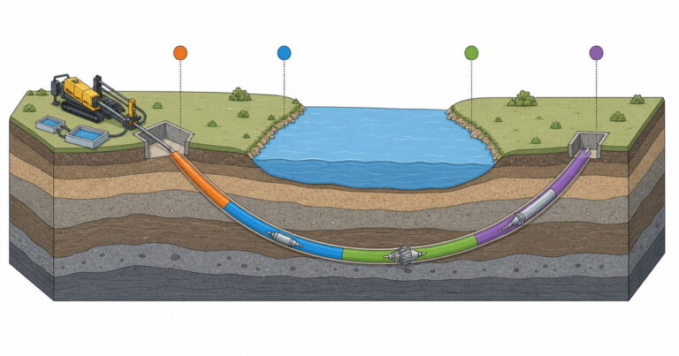
How does horizontal directional drilling work? It drills a small, steerable pilot hole along a designed arc from an entry point to an exit point, enlarges that hole with reaming passes, then pulls the prefabricated product pipe back through the fluid-filled bore in one continuous operation. The horizontal directional drilling process is easiest to follow as four stages: bore planning and site set-up, pilot hole drilling with steering, hole enlargement, and pullback with restoration.
Horizontal directional drilling works in four sequential stages: a pilot hole is steered along a designed arc, reaming passes enlarge it, the product pipe is pulled back in one continuous run, and the surface is restored. Each stage fixes the next: alignment, pull load and annular pressure.

How Does Horizontal Directional Drilling Work in Four Stages?
An HDD crossing is surface-launched: the rig stays above ground and drives a steerable bore on a designed arc from entry to exit, so no launch shaft is excavated.
- Plan and set up. Fix the bore profile, pits, rig pad, clearances and fluid plan before the bit turns.
- Drill the pilot hole. Track and steer a small bore along the design arc, correcting as the head advances.
- Enlarge the hole. Pull progressively larger reamers through to open the bore to its final diameter.
- Pull and restore. Pull the prefabricated pipe back through the bore and close out the site.
Time is not split evenly, and it changes with length, diameter and ground. The table below shows typical on-site effort for supported crossings.
| Stage | What actually happens | Typical share of on-site time | Governing parameter |
|---|---|---|---|
| 1. Bore planning and site set-up | Bore profile and clearance design, geotechnical review, pits, rig pad, fluid mixing and recycling, utility locates | Planning: weeks to months; on-site set-up: 5–15% | Entry and exit angle, bend radius, depth of cover |
| 2. Pilot hole drilling with steering | A steerable head follows the designed arc; surveys between rod joints correct the heading | 30–45% | Bend radius, steering response, guidance range |
| 3. Hole enlargement (reaming) | Reamers are pulled or pushed through in multiple passes until the bore reaches its final diameter | 25–40% | Ream ratio, cuttings volume, annular pressure |
| 4. Pullback and restoration | Product pipe is pulled in behind a reamer on a swivel; pits are backfilled and the surface is reinstated | 10–25% | Pull load, drag, product pipe curvature limit |
Stage 1: Bore Planning and Site Set-Up
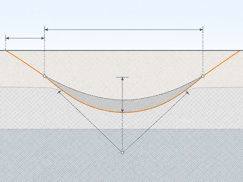
The horizontal directional drilling process starts here. The bore profile runs as curves and straights between entry and exit, satisfying the bend radius of the drill rod, the bend radius the pipe accepts, and the cover required under the obstacle.
Entry and exit angle. Published practice puts entry angles between 8° and 20°, with about 12° often ideal and rigs frequently at 12° to 16°. Exit angles are usually lower, commonly 5° to 12°. Angle and target depth together fix the set-back distance from the obstacle.
Bend radius. A common rule of thumb is a minimum radius of about 1,000-1,200 times the nominal pipe diameter, or roughly 100 ft per inch. The allowable cold bend radius of steel pipe can be tighter, which is why pipe following a curved bore is often bent deliberately before pullback. Our pipeline cold bending capability exists for that.
Site set-up. Site set-up is substantial: entry and exit pits sized for the entry angle and swivel assembly, a rig pad, a fluid system with mixing and containment, the joined pipe string, and utility locates with clearances from the bore path.
Stage 2: Pilot Hole Drilling with Steering
The pilot hole is the alignment of the crossing. It is drilled far smaller than the pipe and steered to reach the exit point at the design depth and angle. A pilot hole that drifts at depth cannot be corrected later without re-drilling.
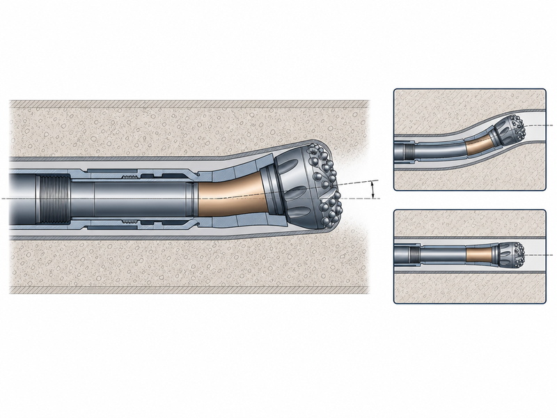
How the curve is produced. Steering comes from asymmetry at the bit. The leading assembly carries an angular offset — a bent sub, or a bent motor housing in rock — so the bit face is not aligned with the string axis. The operator controls the orientation, or tool face, of that offset:
- Sliding. With the string held against rotation, the offset pushes the bit to one side and the bore builds curvature in the direction the tool face points.
- Rotating. With the string rotating, the offset sweeps around and its effect averages out, so the bore advances essentially straight.
Steering is a rhythm of slide and rotate, and curvature is held during straight runs.
What limits the bend radius. The practical minimum radius is governed by the drill rod and, for the finished line, the product pipe. Bending tighter than its allowable curvature raises wall stress and can fatigue, buckle or damage it. The 1000-times-diameter rule applies to the alignment, and the drill string’s allowable curvature must also be respected; the tighter of the two controls.
How the head is tracked. Guidance choice is driven by depth and surface access.
| System | How it works | Practical depth and use |
|---|---|---|
| Walkover locating | A transmitter in the drill head is read from the surface along the bore path | Classic systems roughly 9–12 m; modern multi-frequency receivers report tracking deeper. Best where the surface above the bore is accessible. |
| Wireline magnetic guidance | A wire through the drill string feeds a sonde in the head; a surface coil and computer process the signal | Deep and long bores, and crossings where the surface cannot be occupied. |
| Gyroscopic steering | A gyro tracks heading independently of the surface and of magnetic interference | Deep bores and areas of strong electromagnetic interference, such as near power lines or rail signalling. |
The pilot hole is surveyed at each rod joint, and departure from the design profile is corrected on the next slide — early and gently, not late and hard.
Stage 3: Hole Enlargement (Reaming) and the 1.2–1.5× Rule
How many reaming passes does a horizontal directional drilling bore need?
Enlargement answers the middle of the question “how does horizontal directional drilling work”: A reamer is drawn through the bore until the hole reaches its final diameter, balancing speed against keeping cuttings moving without over-pressurising the annulus.
How big the finished hole should be. Good practice calls for a final bore of roughly 1.2 to 1.5 times the product pipe outside diameter; a common alternative is the lesser of the product diameter plus 12 inches, or 1.5 times the product diameter. Both leave enough annulus for the pipe; oversizing wastes effort and fluid, and undersizing raises pull load.
Why reaming is done in passes. A single reamer cannot jump from pilot diameter to a large final diameter, because cuttings volume and fluid demand rise faster than the annulus can clear them. The hole is opened incrementally, and passes grow with pipe size:
- Step increment. Keep each pass to a modest increase so cuttings clear before the next pass.
- Annular clearance. Pipes under roughly 8 in. (200 mm) often need a proportionally larger ream ratio for a wide enough annulus.
- Direction. Backreaming — pulling the reamer toward the rig with the string in tension — is common on long bores, since a string in tension resists buckling better.
- Fluid matching. Each pass raises cuttings volume, so flow rate and viscosity are re-checked as the hole grows.
Moving the cuttings. Annular velocity must lift solids rather than let them settle into a bed, and published HDD hydraulics work suggests keeping the cuttings volume fraction below roughly 30–35%. Beyond that, friction loss climbs and frac-out risk rises, so reaming is staged rather than rushed.
Stage 4: Pullback and Restoration
Pullback installs the line. The pipe, fabricated on the exit side, is connected behind a reamer and pulled through.
Why the pipe must not rotate. A swivel between the product pipe and the reamer decouples rotation: the string may turn, but the pipe is towed straight through without torque. That lets a welded steel line, a coated pipe or a fused HDPE string be installed without twisting its joints, and defines the design case: the pipe resists axial tension and curvature, not torsion.
What the pull load is made of. The tension the rig must develop accumulates along the installed length:
- Frictional drag. The submerged weight of the pipe against the bore wall, multiplied by a friction factor the fluid is designed to reduce.
- Capstan effect. On curved sections, friction is amplified by the wrap of the pipe around the bend, so load builds faster than on a straight bore.
- Hydrokinetic drag and buoyancy. Displacing fluid generates resistance while also giving buoyant support, depending on whether the pipe is ballasted or flooded.
Because drag accumulates, pullback runs continuously: stopping lets the pipe settle into the cuttings bed and raises the breakout force to restart. A commonly quoted pullback rate is around 100 m per hour in favourable ground, but it is sensitive to curvature, ground and remaining cuttings.
Restoration and close-out. Entry and exit pits are backfilled and compacted, the rig pad is removed, fluid returns are contained, and the surface is reinstated. The installed line is surveyed for as-built position and, for a pressure line, tested through our pipeline inspection service before service.
Drilling Fluid and Annular Pressure: Why Frac-Out Happens
A bentonite-based fluid, often built with polymers, cools and lubricates the bit, lifts cuttings, deposits a thin filter cake that stabilises the bore wall, and supports the bore against collapse.
The pressure that matters. Pumping fluid down the string and back up the annulus creates pressure against the bore wall. Part is hydrostatic, set by fluid density and depth; part is friction loss, which grows with viscosity, flow rate and bore length.
Why frac-out happens. Annular pressure is where the question “how does horizontal directional drilling work” becomes a safety issue.
A frac-out, or inadvertent return, occurs when annular pressure exceeds the fracture gradient of the overlying soil: the fluid reaches the surface. Fracture gradients are commonly estimated at about 0.7 to 1.0 psi per foot of overburden depth, so the margin is thinnest where the bore is shallow. FERC publishes guidance requiring HDD monitoring, inadvertent return response and contingency planning on regulated US crossings.
Frac-out is managed with the same levers that set the pressure:
- Fluid density. Keep the mix as light as the ground allows.
- Flow rate. Pump only what is needed to clear cuttings; excess rate adds friction pressure without a cleaning benefit.
- Viscosity and gel strength. Balance hole cleaning against friction loss.
- Advance rate and monitoring. Control the cuttings volume in the annulus, and use downhole pressure transmitters plus inlet-versus-return volume checks to warn before fluid reaches the surface.
What Can Go Wrong? Failure Modes, Causes and Prevention
What causes an HDD crossing to fail, and how is it prevented?
The table below sets out the failure modes our field teams plan against, with causes, warning signs and controls.
| Failure mode | Cause | Warning sign | Prevention |
|---|---|---|---|
| Frac-out / inadvertent return | Annular pressure exceeds the fracture gradient of the overlying soil, usually in shallow or permeable ground | Reduced returns at the pit; fluid or discoloured ground at the surface | Light fluid, controlled flow rate, staged advance, pressure monitoring and a documented response plan |
| Stuck pipe / string | The pipe settles into a cuttings bed during a stoppage, or the bore closes on the string | Rising pull or thrust force and a drop in penetration rate | Continuous pull, adequate hole cleaning, correct fluid, and early reaction to a load increase |
| Hole collapse | Cohesionless or friable ground with insufficient fluid support | Torque spikes, erratic returns and cuttings slugs at the pit | Higher fluid density and filter cake, controlled ream ratio, and slower advance |
| Lost circulation | Fluid escapes into a permeable or fractured formation through the bore wall | Falling fluid level in the pit and reduced return volume | Loss-control additives, well-matched fluid, and reduced annular pressure |
| Utility strike | The bore path conflicts with an unmapped or mis-located service | Unexpected resistance or returns; tracking departure near a known service | Complete utility locates, mandatory clearances and designed separation |
The geotechnical investigation, utility locates and bore profile turn these risks into priced line items.
Scope of Application: When the Four-Stage Sequence Applies
The four-stage sequence applies where the product can be pulled rather than pushed, the pipe tolerates the bore curve, and the ground holds a fluid-supported hole: pressure pipelines, conduits, cables and casings.
- Gravity-flow lines: the bore cannot hold a constant fall, so use microtunneling or another guided jacking method.
- Cohesionless gravel and cobbles: the hole will not stand, so use a casing-first method such as auger boring.
- Short, shallow crossings in well-characterised ground: open cut is usually cheaper and easier to inspect.
How This Changes by Project Role
What matters most when planning the horizontal directional drilling sequence?
In our experience, the pilot hole fixes everything downstream, so spend the effort on the profile, the bend-radius check and the geotechnical investigation, not the rig.
How should a contractor schedule the stages of an HDD crossing?
Planning and set-up are fixed days, reaming and pullback scale with length and diameter, and fluid handling runs throughout – so schedule them as separate activities.
What should a QA engineer watch during an HDD pullback?
On the crossings we have supported, our field teams record three things above all: annular pressure against the fracture gradient, pull load against the allowable, and the fluid returns.
Frequently Asked Questions
These are the questions about the HDD crossing sequence we field most often.
How does horizontal directional drilling work step by step?
The crossing runs pilot hole, reaming, pullback, then restoration. One or more reaming passes enlarge it to roughly 1.2 to 1.5 times the pipe diameter. The pipe is then pulled back on a swivel, and the pits and surface are restored.
How long does a horizontal directional drilling crossing take?
It depends on length and ground. We have seen pilot hole drilling take the largest share of on-site time, reaming the next largest and pullback the smallest. A small utility bore in favourable soil can be drilled, reamed and pulled in within a day; a long, large-diameter rock crossing can run for several weeks.
Why can an HDD pilot hole only bend so sharply?
The curve is limited by the minimum bend radius of the drill rod and the product pipe. A common rule of thumb is a curvature radius of roughly 1,000-1,200 times the nominal pipe diameter, which is about 100 ft of radius per inch of diameter. Bending tighter raises wall stress and can buckle or damage the component.
What is the difference between the pilot hole and the reamed hole?
The pilot hole guides the crossing; the reamed hole receives the pipe. The pilot hole is the small bore drilled first, and it fixes the alignment. The reamed hole is the enlarged bore produced by pulling progressively larger reamers through it, sized to roughly 1.2 to 1.5 times the product pipe outside diameter.
How does drilling fluid pressure cause a frac-out at the surface?
The annular pressure exceeds what the ground can hold. Drilling fluid is pumped in to carry cuttings and stabilise the hole, and it develops pressure in the annulus. A frac-out happens when that pressure exceeds the fracture gradient of the overlying soil and the fluid escapes to the surface.
Key Takeaways
The short answer to “how does horizontal directional drilling work” is a steerable pilot hole, a reamed hole and one continuous pull. The horizontal directional drilling process is sequential: each stage fixes the next one’s conditions.
- Planning fixes everything downstream. Entry and exit angle, minimum bend radius and depth of cover set the bore profile, and the pilot hole fixes the alignment.
- Steering is slide and rotate. A bent offset at the bit builds curvature when the string slides and cancels out when it rotates, within the allowable bend radius of rod and pipe.
- The hole is opened in passes. A final bore of roughly 1.2 to 1.5 times the pipe diameter, opened incrementally, keeps cuttings and annular pressure manageable.
- Pipe is pulled, not turned. A swivel decouples rotation, and pull load accumulates through drag, capstan effect and hydrokinetic resistance.
- Fluid pressure is the main environmental risk. Frac-out occurs when annular pressure beats the fracture gradient, so fluid design and pressure monitoring are the primary controls.
How JSW Supports HDD Crossings
JSW is a pipeline engineering and construction company that executes trenchless crossings with its own crews and equipment. Our scope covers HDD crossing services, trenchless technologies for constrained and sensitive sites, pipe preparation through pipeline cold bending, verification by pipeline inspection, and the full บริการติดตั้งท่อส่ง chain that connects them.
Because we engineer and execute the work ourselves, our crossing plans are built from site geotechnics and utility clearances rather than from a template, and the bore profile, reaming schedule and fluid plan are documented before mobilisation.
- Integrated delivery: design, drilling, pipe fabrication, installation, testing and restoration under one scope.
- Auditable process data: bore surveys, pull-load records and fluid volumes documented through the crossing.
- Risk-explicit pricing: named, priced contingencies for the failure modes that actually stop crossings.
- Safety and compliance: activities worked to recognised standards, including OSHA excavation rules and API 1104 welding practice where they apply.
Planning an HDD crossing and want the sequence checked against your data? Send your alignment, geotechnical information and pipe specification for a free technical review. Our engineers respond with a stage-by-stage method statement and a budget range.
The question “how does horizontal directional drilling work” is answered on site by the four stages above: a planned pilot hole, steering within the allowable bend radius, incremental reaming and one monitored pull.





































 English
  Arabic
  Russian
  Spanish
  French
  Vietnamese
  Polish
  Thai
Thai  Indonesian
  Turkish
  Portuguese