

An HDD river crossing design is the geometry and burial solution that carries a pipeline under a watercourse: a bore path whose entry angle, exit angle, setback, curvature and depth below the bed can all be achieved with the rig, ground and working areas that exist. This guide is written for owners, designers and reviewers fixing those decisions before mobilisation. It works through angle selection, the scour and migration that drive depth, the geotechnical profile, and the loads a flood event adds.
What Does HDD River Crossing Design Have to Decide?
An HDD river crossing fixes four unknowns together: bore path geometry, target depth, bore length and alignment, and none can be settled alone.
- Bore path geometry: entry angle, exit angle, curvature between them, and the horizontal setback each angle forces on the bank.
- Target depth: how far below the design bed level the pipe must sit once scour and channel movement are accounted for.
- Bore length: the consequence of depth, angles and the width of the channel plus its floodplain.
- Alignment: where the bore has to land on each bank to meet the route within tie-in tolerance.
A defensible HDD river crossing design holds those four against constraints: the rig’s ability to drill and pull, the curvature the drill string and pipe tolerate, and the ground the bore passes through. ASTM F1962, the standard guide for maxi-HDD placement under obstacles including river crossings, and ASCE Manual of Practice 108 treat a crossing as a combined geometry and stress problem.
Every figure quoted here is an input to project-specific design and must be confirmed by a competent engineer for the actual crossing.
How Are Entry and Exit Angles Chosen for a Water Crossing?
Entry and exit angles are commonly quoted in the 8° to 18° band, and they are an output of the geometry: the angle buys depth, and depth buys clearance under the bed. Four things set it:
- Rate of depth gain: a steeper angle reaches the required cover in a shorter horizontal distance, which matters when the bank offers little space.
- Curvature at the transition: the arc from horizontal to the entry angle must respect the bend radius of the drill pipe and of the product pipe.
- Rig capability: thrust, torque, rod handling, mast and anchor geometry all limit how steeply the bore can be drilled and steered.
- Surface constraints: the entry pit, rig pad, anchor pattern and pipe string corridor must fit between the bank and the nearest obstruction.
Bend radius under a river is the curvature limit the bore must respect, set by the drill string and the product pipe, and it fixes how much setback each angle consumes on the bank.
As planning aids rather than design values, drill pipe radius is often estimated at roughly 100 to 200 ft per inch of pipe diameter, and HDPE product pipe at about 25 to 35 × outside diameter. A widely used setback rule of thumb for a directionally straight profile is 5:1, five units of horizontal distance per unit of depth, an effective angle of about 11°.
Table 1 shows the trade-off at a glance: at each entry or exit angle, how much depth a 100 m inclined bore gains and how much horizontal run reaches 15 m of depth.
| Entry or exit angle | Depth gained per 100 m of inclined bore | Run needed to gain 15 m of depth | Typical planning fit |
|---|---|---|---|
| 8° | about 14 m | about 107 m | Wide banks; lowest curvature demand |
| 12° | about 21 m | about 71 m | Balanced start; moderate curvature demand |
| 15° | about 26 m | about 56 m | Constrained banks; elevated curvature demand |
| 18° | about 31 m | about 46 m | Shortest setback; highest curvature and pull load |
Halving the horizontal run roughly doubles the curvature demand at the transition, so a steeper angle only helps where the string and the pipe can accept that curvature. In our design reviews, angle selection is usually settled by the setback available at the entry bank rather than by the geology under the channel. The inputs that most often move that decision are the surveyed bank width, the anchor pattern and the tie-in tolerance; where none is surveyed, the geometry is not ready to fix.
What Sets the Target Depth and Length Under the River Bed?
How does scour depth set minimum burial depth?
Minimum burial depth under a watercourse is a calculation, not a fixed figure: it is measured from the deepest credible bed level that design scour can produce, and the bed surveyed today is only the starting point for that calculation. On any HDD river crossing design, bed lowering is estimated with general, contraction and bend scour relationships of the kind implemented in HEC-RAS-style hydraulic tools for an agreed design flood; cover, survey uncertainty and drilling tolerance are then added. For a reader asking how deep a pipeline should be under a river, the answer here is a method, not a number.
The calculation needs a surveyed bed and bank profile on a stated datum, design flood level and velocity, computed scour with its method recorded, bed material gradation and any armouring layer. Cover above the scour envelope is commonly specified in the 0.9 to 1.5 m range; since the reference is the lowest credible bed level, the distance from pipe to present bed can be several times the land figure.
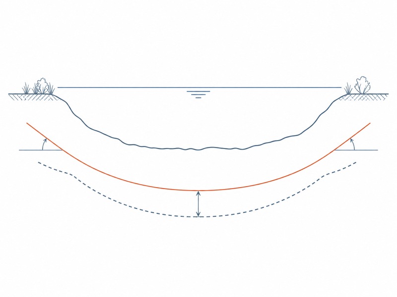
A documented crossing shows the scale that scour can force. The Yangtze River crossing for the Jiangdu-Rudong gas pipeline, completed in 2016, installed twin 711 mm (28 in) pipes over 3,300 m with the minimum buried depth set by section scour depth. That example is a scale reference, not a design basis; the burial depth on any other crossing still has to be calculated from its survey, scour analysis and geotechnical profile.
How do length, depth and angle trade off?
Deeper burial lengthens both approach tangents, so a scour decision becomes a length and pull-load decision. Deepening a 400 m wide crossing from 10 m to 20 m of burial at a 12° entry angle adds roughly 48 m of inclined bore at each bank, about 96 m in total. The arithmetic assumes a straight inclined tangent and no curvature or ground loss, so it shows direction, not a design output.
- Deepen to clear scour: raises length and pull load and lengthens the distance over which guidance error accumulates.
- Steepen the angle to keep the bore short: raises curvature and bending stress against the allowable bend of the pipe.
- Extend the approach to reduce curvature: needs more setback, more land rights and a larger working area.
- Shorten the horizontal section under the bed: saves length but leaves less room for steering corrections.
In practice the geometry is settled by iterating between those four levers until one profile satisfies cover, curvature, pull load and land availability at the same time. On crossings we have supported, the binding constraint was rarely the same on both banks.
What Geotechnical Profile Should the Bore Geometry Follow?
The geotechnical profile through the channel decides how the bore can be drilled, and therefore how deep and how long it can sensibly be. HDD project guidelines call for a geotechnical report covering boreholes, penetration tests and a characterisation profile along the alignment, extended across both banks where access allows. That profile is the document an HDD river crossing design is fitted to.
How does clean sand and gravel change the bore?
Clean sand and gravel is the classic fluid loss case. Permeability is high, the annulus may be unstable, and the pressure needed to clean the hole is the pressure that drives fluid into the formation. Cover is the main defence, and where loose material reaches the bed the fluid plan has to assume some loss.
How do cobbles, boulders and rock head change the bore?
Cobbles and boulders are a steering problem before they are a reaming problem: the bit deflects, and the as-drilled profile drifts from the plan where accuracy matters most. Where they appear near the bed, the usual responses are to hold the bore deeper in a finer layer if one exists and to accept slower penetration. Rock head sets how much cover the arch can hold, and a steep transition from soil to rock is where guidance behaviour changes and tools are most likely to be changed mid-crossing.
Investigation is therefore scoped to answer geometry questions: borehole and test pit spacing related to crossing depth and reamed diameter, SPT or CPT in soils, rock coring with recovery and RQD, groundwater and artesian head, and gradation and abrasivity testing. Our field teams record the soil-to-rock transition as the point where most unplanned tool changes occur.
How Do Buoyancy, Uplift and Flood Events Change the Design?
Buoyancy control in a flooded bore is the load case most often underestimated, because it varies with how the string is filled through the pull.
- Installation buoyancy: a large-diameter pipe filled with air floats in a flooded bore, controlled by filling, ballast weights or restraint of the string.
- Uplift in service: shallow cover and an emptied line allow uplift pressure, and any loss of cover to scour adds to it.
- Flood flow: design flood velocity increases scour, mobilises bed material and exposes the crossing to debris.
- Temporary works: rig pads, pits and containment sit in the floodplain, where a rise of a metre or two stops the works.
Flood stage also shapes the programme. In our experience, buoyancy control drives the cost gap on large-diameter river crossings, not depth alone.
What Do Bank Stability, Landfall and Seasonal Windows Demand?
Bank stability, landfall and the seasonal work window belong inside the HDD river crossing design, not in a separate exercise.
- Pit location: pits should be set back far enough that they do not load or undercut the bank, checked for the worst credible drawdown or flood stage.
- Bank stability: an eroding bank will not hold a rig pad, a pit and an anchor pattern, so shoring, protection or a revised pit position may be needed before the geometry is fixed.
- Landfall: in a tidal or estuarine reach, the landfall may need protection against wave and tidal action, and burial depth may have to satisfy a coastal check as well as the scour check.
- Permitting windows: watercourse crossings are commonly regulated, with restrictions on in-water work during migration or spawning periods and controls on sediment release and fluid handling.
Where the permitted window is narrow, a design that reduces mobilisations or shortens the exposed period is often preferred even if the bore is slightly longer.
Which Risks Decide a River Crossing?
The risk set that shapes an HDD river crossing design is narrower than for a land crossing, because the watercourse changes the consequences of failure. An inadvertent return, or frac-out, reaches open water rather than a field. Table 2 maps each mechanism to the design response and the residual risk.
| Risk | Mechanism on a watercourse | Design response | Residual risk |
|---|---|---|---|
| Scour deeper than assumed | Flood larger than the design event lowers the bed below the computed envelope | Design flood scour with a stated return period, uncertainty allowance, recheck after postponement | Flood-return-driven: low where the design flood is agreed, higher on mobile beds |
| Inadvertent return to the river | Fluid follows permeable strata or a fracture path to the bed | Greater cover in granular zones, loss-tolerant fluid, containment, monitoring and a response plan | Cover-dependent: medium where monitoring and containment are in place |
| Channel migration | The meander belt shifts and moves the thalweg away from the designed profile | Design against a migration corridor rather than one bed line; hold depth across it | Corridor-defined: medium where the migration corridor is wide |
| Thin cover over rock head | Rock rises close to the bed, leaving little ground above the arch | Re-profile deeper in rock if drillable, re-route, or price a short rock interval explicitly | Rock-head-driven: medium to high where cover above the arch is thin |
| Cobbles in the steering interval | The bit deflects and the as-drilled line departs from the plan | Hold the bore in a finer stratum, reduce steering demand, plan for tooling changes | Tooling-dependent: medium, managed by planned changes |
| Artesian groundwater | Inflow changes the fluid balance and the stability of pits and bore | Design for the measured head, expect higher losses, plan containment | Head-driven: medium, managed by designing to the measured head |
| Flood during construction | A freshet floods the pad, pits and containment | Temporary works for a realistic flood stage, flow monitoring, a stop-work trigger | Stage-driven: medium, set by the assumed flood stage |
| Permitted window missed | Seasonal restrictions or delay push works outside the permitted period | Treat the window as a hard constraint, keep restoration inside it | Window-driven: medium, set by the permitted period |
Table 2 screens risks for discussion; each row has to be evaluated against the survey, the geotechnical profile and the hydraulic model for that crossing, and confirmed by a competent engineer before the design is fixed.
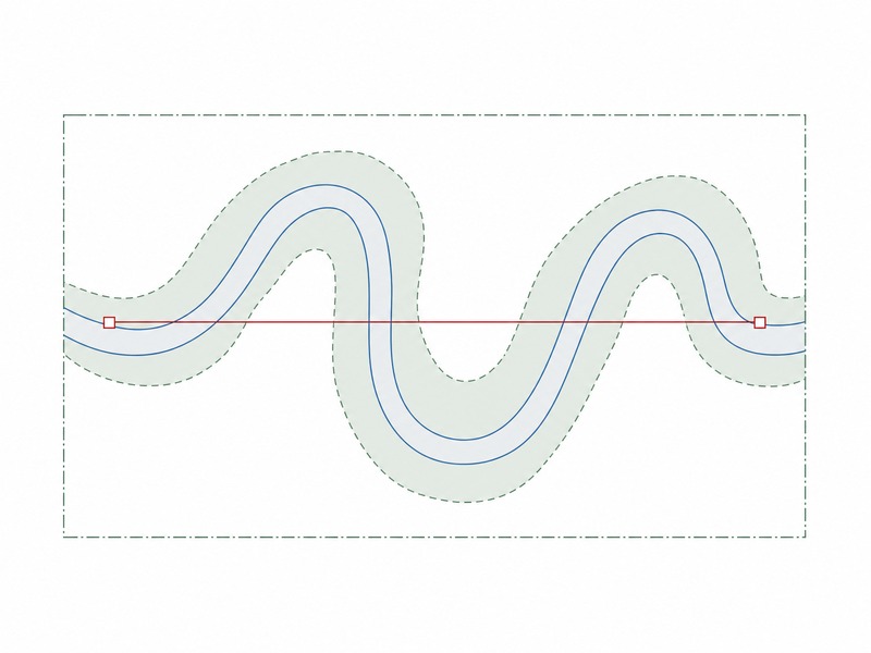
We have seen crossings re-priced late in the programme because the migration corridor was defined after the profile was fixed, and the depth then required changed the whole geometry.
Frequently Asked Questions
What is HDD river crossing design?
HDD river crossing design is the process of fitting a drillable bore path and burial depth under a watercourse. It combines entry and exit angles, bend-radius setback, target depth below the design scour envelope, and the alignment that meets the pipeline route on both banks, all checked against the ground and the rig actually available.
How deep should a pipeline be under a river?
Deep enough to sit below the deepest credible bed level created by design scour, plus the required cover. The figure is site-specific. Minimum burial depth is calculated from general, contraction and bend scour for the design flood, then increased for channel migration, survey uncertainty and drilling tolerance, and confirmed for the site.
What entry angle is used for an HDD river crossing?
Most crossings use entry and exit angles between 8 and 18 degrees. The angle is chosen to gain the required depth inside the setback available on the bank, while keeping curvature within the drill pipe and product pipe limits and staying inside the rig capability.
How is scour depth used to set burial depth?
Scour depth defines the lowest bed level the pipe must clear, so it sets the floor for the design. Engineers compute general, contraction and bend scour for the agreed design flood with standard hydraulic methods, add the required cover and tolerances, and that result becomes the minimum burial depth for the crossing.
Can HDD cross a river in sand and gravel?
Yes, and granular beds are among the most common river conditions for HDD. Clean sand and gravel raise the risk of drilling fluid loss, so the design usually holds deeper cover to increase the distance between the bore and the bed, and the fluid plan assumes some loss rather than relying on full returns.
Why do river crossings cost more than the land sections either side?
Water crossings carry depth, permitting, seasonal and risk costs that land sections do not. Deeper burial lengthens the bore, the permitted work window may be short, fluid containment and monitoring are required, and the chance of loss of returns or a flood event during construction has to be priced into the works.
Key Takeaways
- Minimum burial depth under a watercourse is set by design scour depth and channel migration, not by a fixed figure.
- Entry and exit angles in the 8 to 18 degree band are outputs of the geometry: steeper angles buy depth in less setback but raise curvature and pull load.
- The 5:1 setback rule of thumb corresponds to roughly 11 degrees and is a planning aid, not a design value.
- The geotechnical profile through the channel, especially sand, gravel, cobbles and rock head, decides how deep and how long the bore can be.
- Flood events, buoyancy, uplift and bank stability add load cases that land crossings do not have.
- Every figure here is an input to project-specific design and must be confirmed for the actual crossing by a competent engineer.
How JSW Supports HDD River Crossing Design
JSW is a pipeline engineering and construction company that executes trenchless crossings with its own engineering team, crews and equipment. Our scope covers HDD crossing services and trenchless technologies. automatic pipeline welding, pipeline cold bending and boru hattı döşeme hizmetleri prepare and place the pipe for a watercourse crossing.
Because the same team carries out the HDD river crossing design and then builds the crossing, our recommendations reflect what the equipment and crews can deliver on the bank. We work from surveyed bed profiles and geotechnical characterisation, and we price river-specific risks explicitly.
- Integrated delivery: survey interpretation, bore geometry, burial calculation, pipe fabrication and pullback under one scope.
- Auditable engineering: scour inputs, fluid plans and installation records documented for construction review and integrity management.
- Risk-explicit pricing: fluid loss, cobble intervals or a short permitted window stated with their triggers.
- Watercourse experience: river, tidal and floodplain crossings with permitting, containment and restoration in scope.
Working on a river or watercourse crossing with a surveyed bed profile? Send your bathymetric survey, bed and bank profile, geotechnical report, pipe data and permitted work window for a free technical review. Our engineers respond with the four coupled decisions this design turns on, the risks we see and a budget range.





































 English
  Arabic
  Russian
  Spanish
  French
  Vietnamese
  Polish
  Thai
Thai  Indonesian
  Turkish
  Portuguese