
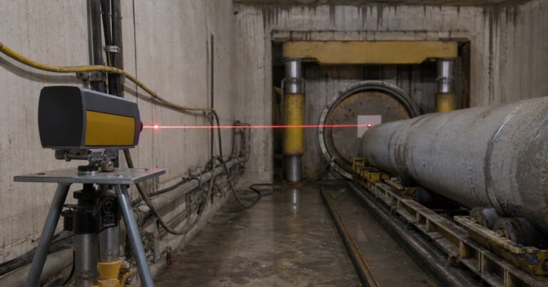
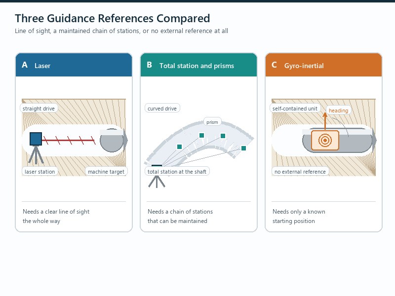
A microtunneling guidance system is the instrument chain that keeps a machine on line and grade in a bore nobody can see into. The three technologies differ less in accuracy than in what each needs to work: a laser target system needs a clear line of sight, a total station network needs a maintainable chain of stations, and gyro guidance needs only a known start point. This comparison maps drive type, length and diameter to a guidance choice.
This comparison covers the three jobs a guidance system performs, where each technology stops, how the accuracy budget is built and matched to the alignment tolerance, and which failure signatures to watch for.
Which Guidance System Fits Which Drive?
Match a microtunneling guidance system to the alignment: a laser suits straight drives up to about 200 m, while a total station network or gyro guidance carries curved or longer drives.
Published specification practice treats this as a two-option decision: a laser target system indicated to about 200 m, and an MTBM (microtunnel boring machine) gyro system beyond that, both for straight or curved drives, with a minimum tunnel diameter of the order of 900 mm. In our experience the move to a total station network or a gyro is driven by a curve, a deep drive with no surface access, or a tolerance with no room for accumulated error.
Steering, Surveying and Auditing Are Three Different Jobs
A microtunneling guidance system is often described as though it were one instrument. In practice it does three separable jobs, and confusing them is how projects buy more capability than they need.
- Steering. The operator needs a continuous, live indication of where the machine is relative to line and grade, fast enough to make a correction before the deviation grows. This is a real-time function, and the update interval matters more than the absolute accuracy.
- Surveying. The drive needs a record of where the machine was at defined points, checked against design grade, so the as-built position can be reconstructed afterwards.
- Auditing. Because any instrument can drift, the guidance needs an independent check that its readings are still true. Auditing is the function most often under-specified, and it is the one that decides whether an out-of-tolerance drive is discovered during the drive or after it.
How Each Guidance System Works
The three technologies differ in their reference. A laser carries a reference from a fixed station through the bore; a total station re-measures a chain of stations; a gyro establishes direction from the earth’s rotation. Everything else – accuracy, curve capability, cost and failure mode – follows from that difference.
How a Laser Target System Works, and Where It Stops
Use a laser target system when the drive is straight and in clear line of sight of the shaft, typically up to about 200 m.
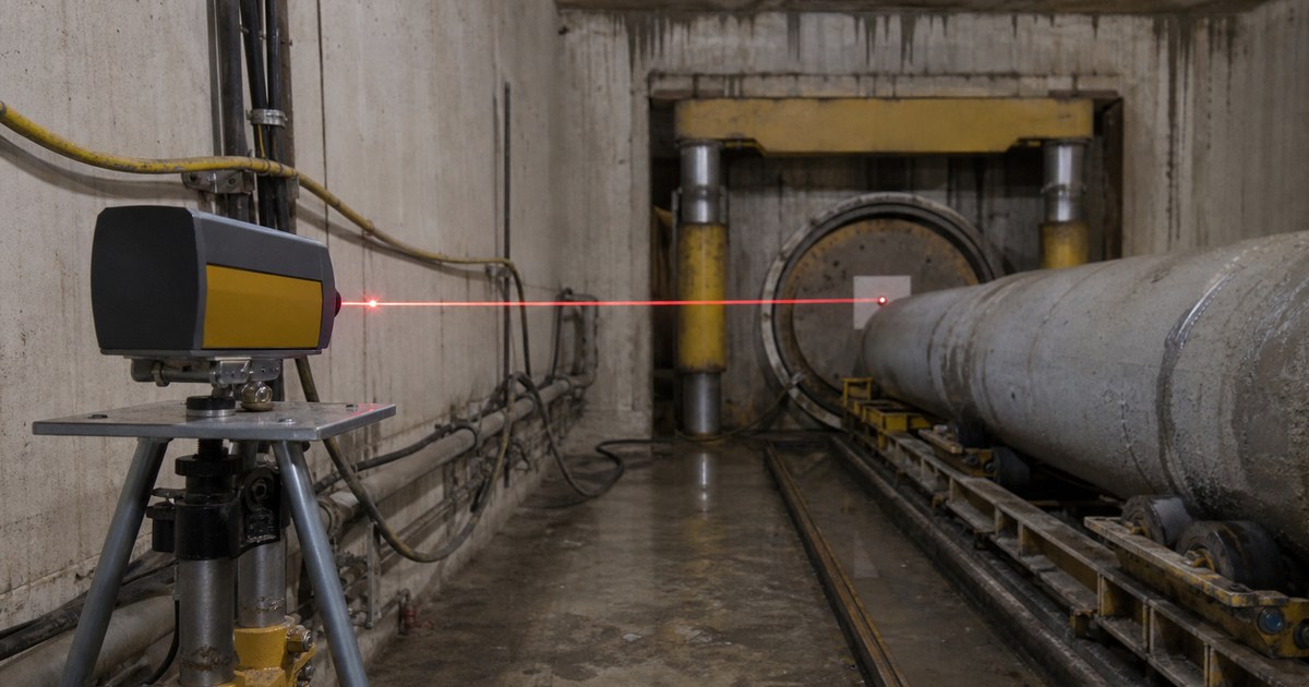
The shaft station reference laser is positioned on line and grade behind the jacking frame and protected from disturbance, and the beam is projected down the tunnel onto an active target mounted in the back center of the machine. Inclinometers at the target, rear and front of the machine track roll, incline and pitch, and feed the operator’s console alongside the target reading.
Two physical limits apply. First, the beam weakens and disperses with distance, and tunnel humidity and temperature variation can bend it – ventilation reduces this. Second, a laser target system cannot be configured for curved alignments, because the line of sight is interrupted. Active laser navigation is typically recommended for straight drives of about 700 ft (roughly 215 m) or less.
How a Total Station System Works, and Why It Handles Curves
Use a total station network when the drive is long or curved, or when line of sight from the shaft cannot be maintained.
A total station guidance system (also called an azimuth network) replaces the single beam with a network of self-leveling station units and measurement prisms, so it can follow a curved alignment where the laser cannot. A shaft station is placed behind the thrust wall on a self-leveling tribrach according to the design axis, and reference prisms are installed on the launch shaft wall to fix bearing. Pipe stations are added along the alignment, typically the first at around 300 linear feet, so line of sight is maintained between stations rather than all the way back to the shaft.
The practical benefit is range and curve capability. Published manufacturer guidance puts the achievable range for this type of network at roughly 1,000 to 3,500 linear feet, depending on prism size, tunnel diameter and atmospheric conditions, and treats it as most economical on straight and curved critical alignments exceeding about 700 ft for drives of the order of 48 in internal diameter or larger. It also reduces downtime, because after the initial survey the network maintains its own measurement connection without manual surveying.
How Gyro Guidance Works Without Line of Sight
Use gyro guidance when there is no usable line of sight, or as the independent audit on a long or curved drive.
A gyro instrument measures direction from the rotation of the earth and needs no line of sight. That makes gyro guidance the natural choice where the machine cannot be sighted – long drives, curved drives, or drives where the surface cannot be occupied for a surveying traverse. Its role is twofold: primary guidance on long or curved drives, and an independent survey audit that proves a laser or total-station system has not drifted.
The trade-offs are physical. A gyro is an instrument that must be powered, transported and protected, it is slower to produce a reading than a continuous laser, and its accuracy depends on a disciplined procedure. Published practice therefore treats the gyro as a campaign: a defined set of checks at defined points, rather than a continuous feed.
Laser vs Total Station vs Gyro: Comparison Table
The table below compares the three microtunneling guidance systems.
On cost, judge the whole arrangement rather than the instrument: the laser carries the lowest hardware and set-up burden, the azimuth network adds instrumentation and station maintenance, and the gyro adds an audit campaign and a disciplined procedure – but the decisive cost is usually the consequence of an out-of-tolerance drive, not the instrument.
In short: a laser is the low-cost default for straight, short drives; a gyro adds curve capability and independent auditing where line of sight cannot be maintained.
| Criterion | Laser target system | Total station / azimuth network | Gyro guidance |
|---|---|---|---|
| Reference | Single laser beam from a shaft station | Chain of self-leveling stations and prisms | Earth rotation, no external reference |
| Indicated drive length | Straight drives to about 200 m (about 700 ft) | Of the order of 300 to 1,000 m and beyond, depending on configuration | Beyond about 200 m; primary use on long drives |
| Curved alignment | Straight drives only: the beam requires an uninterrupted line of sight | Supported | Supported |
| Line of sight required | Yes, continuously | Between adjacent stations only | No |
| What it reports | Target position, often with independent roll and pitch inclinometers | Position and bearing from a station network | Direction and position from a known start point |
| Typical role | Short and medium straight drives | Long and curved drives needing continuous steering | Long or curved drives, and independent auditing |
| Main risk | Refraction, humidity and beam dispersion at length; unusable on curves | Loss of a station, wrong bearing, ground movement affecting control points | Procedure error, drift between audits, and slower readings |
The Accuracy Budget and the Alignment Tolerance It Has to Meet
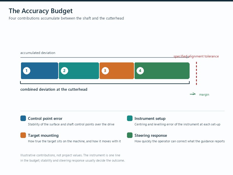
An alignment tolerance is not achieved by buying a better instrument; it is achieved by controlling every contribution to the error. A microtunneling guidance system contributes only part of the total, spent deliberately across control points, instrument, target mounting and steering response.
- Control points. Construction control points must be established far enough from the works not to be affected by construction ground movement, and checked regularly against permanent benchmarks. A survey reference that moves by 20 mm takes the whole drive with it.
- Instrument and calibration. Setup on line and grade, protected from disturbance, with calibration verified before launch.
- Target and inclinometer mounting. Target position and inclinometer alignment relative to the machine axis have to be verified, because every reading is corrected against them.
- Steering response. Articulated steering corrects in increments, so the machine has to be corrected before the deviation reaches the limit rather than at it.
Where the drive must hold a tight tolerance, published allowances for gravity sewers are of the order of plus or minus 50 mm horizontally, plus or minus 30 mm vertically and plus or minus 0.25% on tunnel grade.
| Application | Horizontal | Vertical | Grade | Yorum |
|---|---|---|---|---|
| Gravity sewer | ±50 mm | ±30 mm | ±0.25% | No back-fall and no ponding allowed |
| Casing pipe for other applications | ±500 mm | ±100 mm | ±1% | Wider allowance reflects the purpose of the bore |
| General pipe jacking, stable ground | Typically ±50 mm of true line and level at any point | – | Finer tolerances may not be attainable in unstable ground | |
Applies to: published planning allowances for gravity sewers and casing pipes, used to compare guidance options and to set the accuracy any tracking system has to deliver. Not applicable where: the owner’s specification sets a project-specific alignment tolerance – that value governs the drive and must be confirmed by the guidance supplier and a competent engineer before launch.
Selection Matrix, Set-Up Discipline and the Audit Campaign
The matrix below is the working version we use when a guidance choice has to be defended in a bid. It starts from the alignment rather than the instrument, because alignment is the constraint that cannot be negotiated later. For an owner or EPC it frames the audit arrangement that must be agreed before launch; for a contractor or bidder it frames what has to be documented and priced.
| Drive characteristic | Usual guidance choice | What still has to be verified |
|---|---|---|
| Straight drive, with line of sight from the shaft | Laser | Ventilation and humidity control to limit refraction at length |
| Straight drive longer than about 200 m | Total station network or gyro, with laser as a secondary check | Station spacing, prism size and atmospheric conditions |
| Curved drive at any length | Azimuth network or gyro | Joint deflection allowance and machine steering authority |
| Small diameter, no practical gyro access | Machine-based system with a documented accuracy audit method | How accuracy is maintained and audited without a gyro campaign |
| Tight alignment tolerance | The system that gives the shortest error chain, whatever the length | Control point stability, target mounting and steering response |
Set-up discipline is what makes any of these systems work. The station goes on line and grade behind the jacking frame and is protected from disturbance; the machine is launched only after the jacking cradle and machine are verified on line, grade and level.
The audit campaign closes the loop. Where a gyro is used to audit a machine-based guidance system, checks are typically placed of the order of 120 to 170 m from the drive start and about 100 m from the drive finish (a published planning interval, not a fixed rule). Where the tunnel has man access but not enough space for a successful gyro campaign – typical diameters of about 900 mm to 1,500 mm – the contractor has to document, in advance, a method for maintaining and auditing the accuracy of the machine-based guidance.
Bottom line: if the alignment tolerance is breached, excavation stops, and no corrective action is taken without owner approval. That single rule is why the audit arrangement deserves more attention at bid stage than the instrument’s datasheet.
Guidance Failure Signatures and What They Cost
In our construction reviews, guidance problems almost never announce themselves as instrument faults.
The most common guidance failure is a slow, one-directional drift that is misread as normal steering correction, not a sudden instrument fault.
| Symptom | Likely cause | Immediate action |
|---|---|---|
| Target reading becomes unstable or weak at length | Refraction, humidity, temperature gradient or beam dispersion | Improve ventilation, shorten the sight path, audit position independently |
| Machine steers consistently in one direction | Control point moved, or bearing error in the station set-up | Re-shoot control points against permanent benchmarks before steering further |
| Machine position and as-built survey disagree | Target or inclinometer mounting error, or drift in the machine system | Run the audit campaign and correct the mount before advancing |
| Alignment trend matches an unexplained settlement | Ground movement affecting the reference or the pipe string | Stop, review settlement data and confirm the reference before restarting |
| Corrections grow larger each pipe | Steering authority exceeded, or a joint deflection limit being approached | Reduce advance rate and review the alignment against the manufacturer’s permitted deflection |
Key Takeaways
- A microtunneling guidance system does three jobs – steering, surveying and auditing – and the audit function is the one most often under-specified.
- Laser target systems are the simplest option for straight drives to about 200 m and cannot be configured for curves.
- Azimuth networks maintain their own measurement chain and suit long and curved drives; gyro guidance needs no line of sight at all.
- Alignment tolerance is delivered by control point stability, target mounting and steering response as much as by the instrument.
- Machine position is checked and recorded at least twice per pipe, and guidance output is expected at intervals of no more than two seconds.
- Gyro audit checks are typically placed about 120 to 170 m from the drive start and about 100 m from the finish; if the tunnel is too small, an alternative audit method must be documented before work starts.
Frequently Asked Questions
How accurate is a microtunneling guidance system?
A microtunneling guidance system does not deliver accuracy on its own. The achievable line and grade is set by the whole chain – control points, instrument calibration, target mounting and steering response – and published gravity sewer allowances of the order of ±50 mm horizontal and ±30 mm vertical assume those parts are controlled.
Can a laser target system be used on a curved drive?
No. A laser target system cannot be used on a curved drive: active laser systems depend on an uninterrupted line of sight from the shaft station to the target on the machine, so they cannot be configured for curved alignments. Curved drives need a system that re-establishes its own reference, such as a total-station or azimuth network, or a gyro guidance system (a gyro-inertial instrument).
When should gyro guidance be used instead of a laser?
When the drive is longer than roughly 200 m, when it curves, or when no reliable line of sight exists. Published guidance treats the laser target system and the machine gyro system as the two standard options, with the laser target system indicated to about 200 m and the gyro system beyond that.
What is a gyro audit campaign, and why does it matter?
A gyro audit campaign is an independent check that the machine’s own guidance has not drifted, using a separate gyro survey at defined points along the drive. Checks are typically placed of the order of 120 to 170 m from the drive start and about 100 m from the drive finish, and where the tunnel is too small for a campaign the contractor has to document another method for maintaining and auditing guidance accuracy.
How often should machine position be checked and recorded?
At least twice per installed pipe, with the position recorded against design grade in the shift report. Published specification practice also requires the guidance system itself to report distance from the launch shaft, roll, inclination and attitude across the articulated section at intervals of no more than two seconds.
What happens if the drive goes outside the alignment tolerance?
If the drive goes outside its alignment tolerance, excavation stops. Under published specification practice the tunnel is not to be restarted until the owner directs it, corrective works are the contractor’s responsibility, and no corrective action is to be taken without approval.
How JSW Supports Guidance Set-Up and Survey Control
JSW is a pipeline engineering and construction company that executes trenchless crossings with its own crews and equipment. Our scope covers microtunneling construction, trenchless technologies, HDD crossing services and boru hattı döşeme hizmetleri, and we run our microtunneling drives with laser guidance held to about ±25 mm of true line and grade on the drives we control, with interjack stations deployed roughly every 100 to 150 m on extended drives.
Because we hold the survey and the steering in the same team as the drive, the guidance choice is made against the alignment, not the brochure: the audit arrangement, the target mounting and the control point stability are all fixed before launch, so the tolerance is a plan rather than a hope.
- Alignment-first selection: the guidance method is chosen from drive length, curve geometry and required tolerance, not from instrument availability.
- Audit planned before launch: the independent verification method is agreed at bid stage, including the alternative where the diameter rules out a gyro campaign.
- Recorded position data: machine position, roll, inclination and attitude are logged so the as-built record can be reconstructed.
- Certified delivery: our trenchless work is delivered under ISO 9001:2015, ISO 14001:2015 and ISO 45001:2018 certified management systems.
Need a guidance and survey arrangement that will withstand scrutiny at handover? Send your alignment, drive length, diameter and required tolerance for a free technical review. Our engineers respond with a scoped guidance recommendation and an indicative budget range.





































 English
  Arabic
  Russian
  Spanish
  French
  Vietnamese
  Polish
  Thai
Thai  Indonesian
  Turkish
  Portuguese