
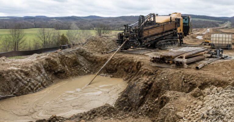
A frac-out in HDD is the unintended loss of drilling fluid from the borehole to the ground surface at points other than the entry and exit points. It is one of the few trenchless failure modes that can be seen from the air, reported by a passer-by, or found in a stream before the crew knows anything has happened. Understanding it means working through three things: the pressure balance inside the bore, the geology that decides how much pressure the ground will accept, and the commercial and regulatory consequences that follow the fluid once it reaches daylight.
What Is a Frac-Out in HDD?
In normal industry usage, a frac-out in HDD is a loss of drilling fluid from the bore path to the surface at any location other than the two points where the bore is designed to return to surface. Ordinary returns arrive at the entry pit by design; a frac-out arrives anywhere else.
Three terms appear in the same permit file and are routinely confused: a frac-out, an inadvertent return, and a spill.
- What it is: drilling fluid reaching the surface away from the entry and exit points.
- What it is not: normal returns at the entry pit, or fluid spilled at the rig, the mixing area or the pipeline itself.
- Why the name: the pathway is opened by hydraulic pressure, so the event is a hydraulic fracture, shortened in field speech to frac-out.
- Why the alias: regulators and specifications more often call the same event an inadvertent return, which is why both terms appear in one permit document.
Applies to every fluid loss outside the entry and exit pits, whatever the volume: fluid arriving at the entry pit is a housekeeping matter, while fluid arriving in a field drain or a ditch hundreds of metres off the alignment is an inadvertent return that triggers notification, containment and reporting duties before the crossing can continue.
Design guidance treats the pressure that causes it as a calculated limit rather than a field judgement. ASCE Manual of Practice 108 and the NASTT HDD Good Practices Guidelines both frame maximum allowable drilling-fluid pressure as a design input, and under FERC-regulated projects and comparable state regimes the same limit is checked again through an HDD plan and a written response plan.
How does a frac-out actually happen when returns stop?
The mechanism is a pressure comparison. Drilling fluid in the annulus pushes outward on the bore wall with a pressure set by mud weight, depth, flow rate and the weight of the cuttings carried in the column. The ground resists with confining stress from the overburden and lateral earth pressure. While annular pressure stays below what the formation can hold, the bore behaves normally.
Annular flow is also the pressure-relief pathway. Slurry moving back along the bore carries pressure away toward the exit, and return flow at the exit pit is the visible proof that the relief is working. When flow slows or stops, that release path narrows: the fluid column no longer carries moving fluid with it, cuttings settle and load the column, and a frac-out in HDD becomes possible.
Baroid Industrial Drilling Products describes the same sequence, noting that when flow abates or stops, fluid-column weight plus cuttings loading can build pressure above the overburden. The fluid then finds the weakest path, which is rarely a straight line to surface. It follows a fracture, a bedding plane, an old utility trench or a loose zone until it reaches a permeable horizon or daylight.
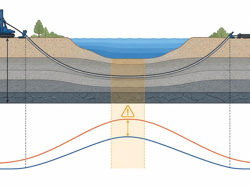
So which argument most often decides the outcome here? Not the maximum pressure achieved, but the margin held at the shallowest point of cover. A crossing can pass every other test and still frac out where the bore comes closest to surface.
How much cover does my bore need before a frac-out becomes likely?
The fracture gradient for the ground above the bore is commonly estimated at roughly 0.7 to 1.0 psi per foot of overburden depth, and that figure sets the maximum allowable annular pressure for the crossing. At 20 ft of cover, the arithmetic gives a working limit on the order of 14 to 20 psi. Because that limit scales with depth, the shallowest cover governs, and a shallower section carries proportionally less margin.
The 0.7 to 1.0 psi per foot band is wide on purpose. It depends on soil type, density, depth, stress history and the presence of any existing fracture, and published sources disagree about which end applies in a given formation. Applies to the ground the value was derived from: re-derive the band for each crossing from its own soil properties and cover profile before it is used as a limit.
The usual basis for the estimate is the cavity-expansion model that originated with Delft Geotechnics in 1997. It treats the bore as a cylindrical cavity expanding in soil and relates the pressure needed to open a pathway to two dominant variables: overburden depth and the friction angle of the soil above the bore. Where cover is thin or the overlying soil has a low friction angle, the allowable pressure falls quickly.
Why do design-stage analysis and field monitoring have to use the same curve? A pressure reading plotted against a limit that was modelled for different soil properties is not a control; it is a chart.
Which Ground Conditions Make a Frac-Out More Likely?
Some ground is simply easier to fracture. The risk factors for a frac-out in HDD cluster around two ideas: how far the fluid has to travel to reach the surface, and whether the ground above the bore already contains a pathway. Frac-out risk then rises with every factor that shortens the path or opens it further.
- Shallow cover – the most common single contributor to frac-out risk. Thin overburden means a low allowable pressure and a short travel path.
- Coarse or loose material – gravel, cobbles, loose sand and fill transmit fluid readily and hold little confining stress, so drilling fluid loss can be rapid.
- Faults and fracture networks – an existing discontinuity can accept fluid at pressures well below the modelled gradient.
- Weathered rock and the rock-soil interface – the transition zone is often the weakest horizon on a rock crossing.
- Artesian conditions – where groundwater is already under pressure, the fluid column has less headroom before the formation takes fluid away.
- Buried services and old trenches – backfill is usually more permeable than the parent soil and can act as a ready-made pathway.
| Causal factor | Mechanism | Early warning |
|---|---|---|
| Shallow cover over the bore | Low allowable pressure and a short travel path to surface | Modelled limit falls close to the calculated bore pressure on the profile |
| Coarse, loose or gravelly overburden | High permeability, little confining stress | Drilling fluid loss without a matching pressure rise; pit level drops |
| Faults, fractures, weathered rock | Existing discontinuity accepts fluid below the gradient | Returns fall while pressure and pump rate stay steady |
| High mud weight or excessive viscosity | Fluid column weight raises downhole pressure directly | Marsh funnel viscosity drifting above the target band |
| Flow stopped with cuttings in the hole | Loss of the relief pathway; cuttings load the column | Pump pressure creep after a stop; cuttings on restart |
| Artesian or high groundwater pressure | Reduced margin before the formation takes fluid | Unexplained pit volume gain early in the bore |
What does a frac-out look like on the surface on a river crossing?
In our experience the first sign is usually a change in the pit, not a change on the ground. Return volume at the exit pit falls, total pit volume drops, and pump pressure may creep up as the fluid finds somewhere else to go. Everything visible at the surface comes later.
Surface signatures to watch for include wet or darkened ground and soft turf away from the pits, discoloration in a ditch or watercourse appearing as a plume, minor ground heave or a fresh crack line above the alignment, and a return flow at the exit pit that does not recover when pump rate is restored. A visible sheen or fluid smell on a watercourse escalates the response immediately.
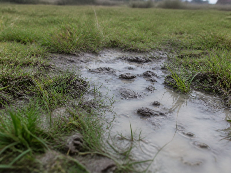
Response timing depends on where the fluid surfaces, not on when the pressure limit was crossed. Fluid that has travelled through a permeable horizon can appear tens of metres from the alignment rather than directly above the bore, which is why permit conditions usually require monitoring along the whole alignment and not only at the crossing centreline.
Which Parameters Do Crews Monitor to Keep Pressure Inside the Limit?
Monitoring exists to answer one question at every rod: is annular pressure still inside the modelled allowable curve? The parameters that answer it are mud weight and Marsh funnel viscosity, the two most direct levers on downhole pressure; gel strength and rheology, measured to API RP 13B-1; pit and total volume, where a falling level with steady pumping means drilling fluid loss and a rising level can indicate formation water entry; circulation pressure and return flow, the pair that shows whether the relief pathway is still open; and downhole pressure from a pressure sub, plotted against the modelled allowable limit rather than watched as a single number.

Our field teams record mud weight and Marsh funnel viscosity at set intervals and cross-check them against the fluid-loss trend rather than treating any single reading as decisive. The monitoring plan should name who acts on a threshold breach, not only what the thresholds are.
Why does a frac-out matter commercially and to the permit file?
Commercially, a frac-out in HDD converts a controlled drilling operation into an environmental response. The immediate cost items are pump and rig downtime while the source is isolated, vacuum and containment equipment, disposal of recovered fluid and impacted soil, and reinstatement of the ground.
Legally, the exposure depends on where the fluid surfaced. The applicant submits an HDD plan and an inadvertent return plan covering monitoring along the alignment, response actions, containment and notification, and continuous examination of drilling-fluid pressures and return flows is a standard permit condition rather than a discretionary good practice.
A release into a watercourse, wetland or protected habitat moves the same event into a different category: agency notification, possible stop-work, sampling, and a permanent record in the permit file. Even a small volume is treated seriously, because turbidity and sediment deposition in habitat matter more than the volume itself.
Reputation belongs on the same list: a release that reaches a public watercourse is remembered by clients and regulators at the next tender.
- Applicant preparing a FERC or state permit file: the frac-out analysis and the inadvertent-return plan are the two documents checked at submission, and continuous pressure and return-flow examination is a standard condition.
- Owner financing a river crossing: the transect where cover is thinnest, not the average depth, sets the frac-out risk carried by the contingency.
- Contractor on a shallow urban road crossing: the governing limit is the shallow cover section, and the permit conditions there usually include monitoring along the whole alignment.
How Severe Can a Frac-Out Be, and How Do Teams Respond?
Severity is usually graded by where the fluid arrives and how much is released, not by the pressure reading that caused it. Response scales with the receptor at risk. The actions and restart criteria for each tier belong to the prevention programme and are set out in the frac-out prevention guide; this table grades the consequence.
| Tier | Description | Consequence and compliance effect |
|---|---|---|
| Tier 1 – minor surface seepage | Small volume at or near surface, no watercourse or sensitive receptor affected | Minor; no notification beyond the plan record, but the pressure margin at that section is now suspect |
| Tier 2 – significant release on land | Larger volume, spreading to a ditch, drain or third-party land | Significant; notification duties attach, and cleanup and disposal become cost items |
| Tier 3 – release to watercourse or sensitive receptor | Fluid reaching flowing water, wetland, habitat or a protected area | Severe; agency notification, possible stop-work order, sampling and a permanent permit record |
The restart decision is the part that gets underestimated. Fluid that has opened a pathway tends to reopen it, so a restart normally has to change something measurable first: pressure, fluid properties, flow rate, or the bore profile itself.
The programme that reduces how often a frac-out in HDD occurs is a separate subject and is covered in its own guide. Prevention and response are different disciplines with different owners on site, and a crossing with a good response plan but no pressure control will use that plan repeatedly.
Frequently Asked Questions
Is a frac-out the same thing as a drilling-fluid spill at the rig?
No. A frac-out is fluid lost from the bore to the surface through the ground; a spill is fluid released at surface from rig equipment or storage. The environmental consequence can look similar, but the causes and the fixes are different.
What depth of cover is needed to avoid a frac-out in HDD?
There is no single universal depth; the governing factor is the allowable pressure at the shallowest point of cover. Because the fracture gradient is lowest where the cover is thinnest, the allowable pressure falls quickly. Site-specific modelling, including the friction angle of the overlying soil, sets the practical minimum for a given crossing.
Does a frac-out always mean the bore or the crossing has failed?
Not necessarily, but it always changes the conditions of the job. Many crossings continue after the pathway is contained and the pressure balance is restored. What a frac-out does mean is that the bore was drilled outside its pressure envelope at some point, so the fluid properties, flow rate or profile have to change before restart.
How quickly can drilling fluid reach the surface after a frac-out?
Fluid can reach the surface in minutes, or it can lag well behind the initiating event. A fracture or an old trench may deliver fluid near the rig almost immediately, while a permeable horizon can carry it tens of metres away and surface it later.
Can a frac-out happen under a river or wetland, and who is notified?
Yes, and that is the case regulators plan for most carefully. Riverbeds, wetlands and watercourses are usually the reason a crossing is drilled rather than trenched, and they are also the receptors with the highest consequence if fluid arrives.
What has to be reported after a frac-out on a river crossing?
Reporting depends on the permit, but the usual expectation is prompt notification plus a written record. Under FERC-regulated and comparable regimes the approved plan sets out monitoring, response actions, containment and collection, and who is notified. Volume, location and corrective action are usually the details that have to be documented.
Key Takeaways
- A frac-out in HDD is drilling fluid reaching the surface away from the entry and exit points.
- The driver is pressure in the bore exceeding what the overlying ground can resist, after which the fluid follows the weakest available pathway.
- Circulation returns are the pressure-relief mechanism; when flow stops, the fluid column and its cuttings can push pressure above the limit.
- The fracture gradient is commonly estimated at roughly 0.7 to 1.0 psi per foot of overburden depth, with the cavity-expansion model used to set maximum allowable pressure.
How JSW Supports Frac-Out Risk Management on HDD Crossings
JSW is a pipeline engineering and construction company that executes trenchless crossings with its own crews and equipment. Our scope covers HDD crossing services, trenchless technologies and boru hattı döşeme hizmetleri, supported by pipeline inspection services and emergency response and contingency maintenance when an event needs a field response rather than a report.
Our approach to frac-out risk is to make the pressure envelope explicit before mobilisation: a modelled allowable pressure along the profile, a monitoring plan that names the thresholds and the person who acts on them, and a response plan agreed with the client before the pilot hole starts. Pricing is risk-explicit rather than optimistic, and monitoring records are kept in a form the client can hand to a regulator.
- One accountable team: crossing design, drilling, installation and reinstatement managed by one team.
- Pressure and volume data: fluid properties, downhole pressure and pit volumes recorded against the modelled limit.
- Limits scoped at bid: pressure limits and response provisions scoped at bid, not discovered on site.
- Permit-led field method: work planned to permit conditions and to recognised HDD good practice.
Planning a crossing in ground that worries you? Send your bore profile, geotechnical data and target fluid properties for a free technical review. Our engineers respond with a scoped recommendation and budget range.
For deeper background, related guides in this series cover the fluid science behind the mud programme, the solids-control equipment that keeps it clean, and the field controls that reduce unintended returns.





































 English
  Arabic
  Russian
  Spanish
  French
  Vietnamese
  Polish
  Thai
Thai  Indonesian
  Turkish
  Portuguese