jasonsong889@gmail.com

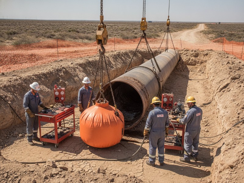
Four pipeline technicians in PPE work on a large steel gas pipeline in a dusty desert trench. An orange inflatable plug is lowered for remote field maintenance.

How High-Pressure Pneumatic Pipeline Plugs Seal Corroded Pipes

High-pressure pneumatic pipeline plugs seal corroded pipes by using deformable elastomer seals, pressure-activated cup designs, and multi-element redundancy to conform to irregular surfaces and prevent leakage. Advanced designs also use segmented expansion and temporary fillers to compensate for corrosion pits and wall loss. What Is a Pipeline Plug? A pipeline plug is a temporary isolation

How High-Pressure Pneumatic Pipeline Plugs Seal Corroded Pipes Baca Selengkapnya »
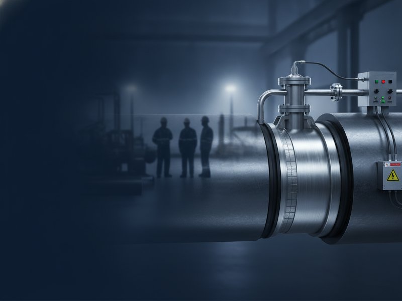
Detailed steel pipeline featuring an expanded plug, hot tap fitting, and bypass valve, in an industrial setting with blurred maintenance crew silhouettes.

How Does a Pipeline Plug Work for Pipeline Isolation? Principles, Types, and Cyclic Pressure Performance

Pipeline Plug Isolation in One Minute Field data shows that over 70% of pipeline isolation failures are linked to improper material selection or installation—not pressure overload. What Is a Pipeline Plug? A pipeline plug is a temporary internal isolation device inserted into a pressurized pipeline to stop flow and create a safe working section without

How Does a Pipeline Plug Work for Pipeline Isolation? Principles, Types, and Cyclic Pressure Performance Baca Selengkapnya »

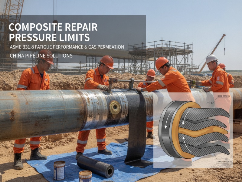
Construction site scene with engineers applying a composite wrap to a large steel pipeline. A technical diagram overlay shows composite repair layers, hoop stress, and load transfer.

How to Repair Through-Wall Gas Pipeline Defects with Engineered Composites: Pressure Limits, Permeation & ASME B31.8 Fatigue Data

Through-wall defects in gas pipelines create an immediate loss of pressure containment and require urgent repair. Engineered composite systems offer a proven solution for restoring up to 100% MAOP without shutdown—when designed to address cyclic fatigue and gas permeation. This guide explains ASME B31.8 and ISO 24817 pressure limits, compares carbon fiber versus glass fiber

How to Repair Through-Wall Gas Pipeline Defects with Engineered Composites: Pressure Limits, Permeation & ASME B31.8 Fatigue Data Baca Selengkapnya »

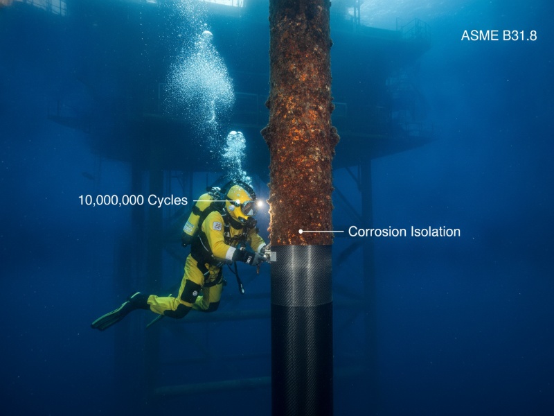
A diver in a yellow suit applies a carbon fiber composite wrap to a corroded offshore riser underwater for corrosion isolation near an oil platform.

Underwater Composite Repair for Corrosion Isolate Offshore Risers: Application Validation Under Severe Wave Action

Underwater composite repair for corrosion isolate offshore risers is a subsea rehabilitation method where carbon fiber wraps bonded with marine-grade epoxy restore mechanical strength and create a permanent corrosion barrier on damaged risers without shutdown or welding. When validated under severe wave action combined with cyclic pressure, carbon fiber systems demonstrate fatigue resistance exceeding 10,000,000

Underwater Composite Repair for Corrosion Isolate Offshore Risers: Application Validation Under Severe Wave Action Baca Selengkapnya »

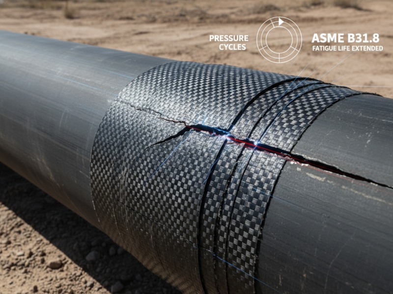
Cracked oil and gas pipeline segment in a desert, reinforced with a dark woven carbon fiber composite wrap. Graphics highlight extended fatigue life under ASME B31.8.

Long-Term Performance of Carbon Fiber Composite Wraps on Cyclic Pressure Pipelines: Mitigating Fatigue Cracking Under ASME B31.8

How Carbon Fiber Composite Wraps Extend Pipeline Fatigue Life (ASME B31.8 Guide) Carbon fiber composite wraps extend pipeline fatigue life by reducing crack tip stress intensity (ΔK) through load sharing, enabling up to 10 million pressure cycles and over 20 years of service under ASME B31.8. What is pipeline fatigue cracking?Pipeline fatigue cracking is the

Long-Term Performance of Carbon Fiber Composite Wraps on Cyclic Pressure Pipelines: Mitigating Fatigue Cracking Under ASME B31.8 Baca Selengkapnya »

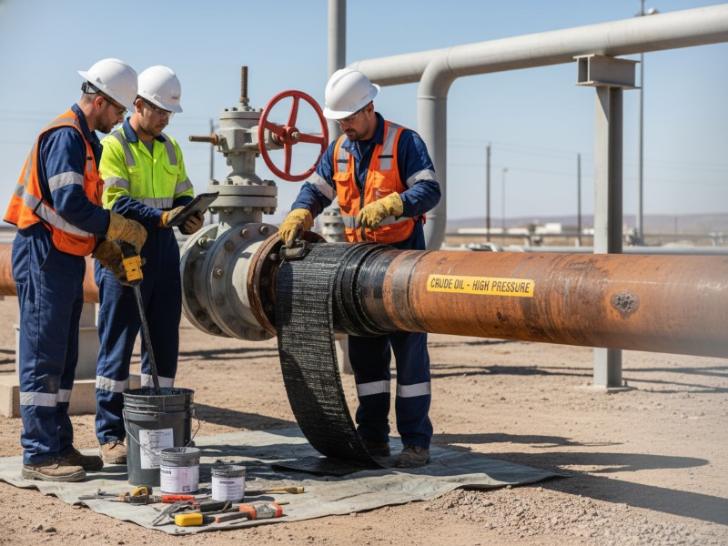
Three technicians in hard hats and reflective gear perform a composite wrap repair on a rusted crude oil pipeline in an outdoor industrial setting with tools.

ISO 24817 vs. ASME PCC-2 Part 4: Composite Wrap Thickness Calculation for High-Pressure Wall Loss Repair

ISO 24817 and ASME PCC-2 Part 4 are standards for composite wrap repair of pressurized pipelines. ISO 24817 uses a performance-based design that allows thinner, optimized repairs based on material testing, while ASME PCC-2 applies stricter safety factors, resulting in thicker and more conservative designs. In practice, ISO is typically used for moderate wall loss

ISO 24817 vs. ASME PCC-2 Part 4: Composite Wrap Thickness Calculation for High-Pressure Wall Loss Repair Baca Selengkapnya »

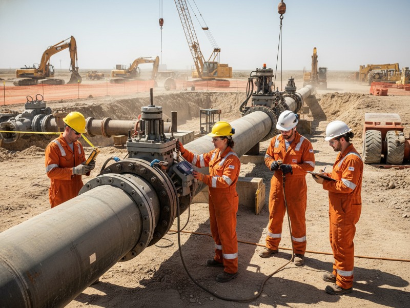
Engineering technicians in safety gear inspect a large steel oil and gas pipeline with field instruments at a dusty construction site featuring excavators.

Pipeline Ovality Limits for Line Stopping (API 570 Guide)

Pipeline ovality is a critical factor in determining whether line stopping can be performed safely under API 570. In practice, ovality above 3% reduces folding-plug sealing effectiveness, while ovality above 5% is typically unacceptable. This guide explains allowable limits, inspection methods, failure mechanisms, and how to decide whether to proceed, compensate, or reject line stopping.

Pipeline Ovality Limits for Line Stopping (API 570 Guide) Baca Selengkapnya »

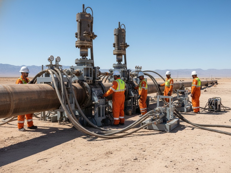
Professional industrial field operation on a large steel oil and gas pipeline in a remote desert, with technicians performing line stopping and hot tapping.

Line Stopping Bypass Calculation (ASME B31.4): How to Prevent High-Velocity Scour in Piggyback Operations

Piggyback line stopping requires diverting 85–95% of total flow through a bypass to keep annular velocity below 2.5 m/s. The required bypass flow is calculated using Q_bypass = Q_total − (V_allow × A_gap). If bypass is undersized, annular velocity can exceed 4–10 m/s, causing severe vibration and rapid stopping bar failure. Quick Calculation Box Bypass

Line Stopping Bypass Calculation (ASME B31.4): How to Prevent High-Velocity Scour in Piggyback Operations Baca Selengkapnya »

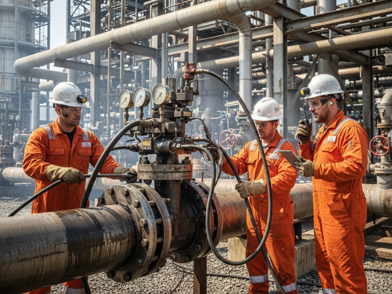
Three pipeline engineers in orange safety coveralls, hard hats, and gloves conducting maintenance on a large industrial steel pipeline with gauges.

DBB Line Stopping in Hot Crude Pipelines (150–260°C): FKM vs FFKM Selection, Testing, and Safety Limits

Best Elastomer for 150°C+ DBB Line Stopping For double block and bleed line stopping in high-temperature crude pipelines, the elastomer selection follows this rule: Elastomer Selection by Temperature Pipeline Condition Recommended Elastomer 150–170°C, low aromatics (<15%) FKM (minimum acceptable) 150–200°C, sour or high-aromatic crude FFKM required 170–200°C (any crude) FFKM recommended 200–260°C (any crude) Only

DBB Line Stopping in Hot Crude Pipelines (150–260°C): FKM vs FFKM Selection, Testing, and Safety Limits Baca Selengkapnya »

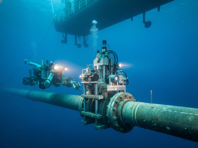
An ROV operates on a subsea pipeline's hot tap clamp in deep blue water. A ship's hull is overhead, with work lights illuminating the industrial scene.

Calculating Minimum Wall Thickness for In-Service Subsea Hot Tapping: Aligning with DNV-RP-F113

The minimum required wall thickness for in-service subsea hot tapping is defined by DNV-RP-F113 as the larger value between burst thickness (governed by internal pressure) and collapse thickness (governed by external hydrostatic pressure), after subtracting corrosion allowance. In deepwater conditions exceeding 700 meters, collapse pressure resistance typically governs the calculation. This guide provides step-by-step calculation

Calculating Minimum Wall Thickness for In-Service Subsea Hot Tapping: Aligning with DNV-RP-F113 Baca Selengkapnya »