

How does CIPP lining work? It works by inserting a resin-impregnated tube into a cleaned host pipe and curing it in place, so the tube and resin become a new structural pipe inside the old one. CIPP lining runs as a numbered 14-step sequence: CCTV inspection, cleaning, flow control and resin wet-out, then inversion, curing, controlled cool-down and lateral reconnection. It fits gravity sewers and pressure mains that still hold their basic shape, within the ASTM F1216 scope of 2 in. to 108 in. (about 50 mm to 2,750 mm).
How Does CIPP Lining Work, Step by Step?
A cured-in-place pipe (CIPP) renewal is a fixed sequence, and the order is not optional. Each stage feeds the next: the survey sets the design, the design sets the tube and resin, the installation sets the position, and the cure log proves the result.
In our lining crews’ logs, the work always breaks down into the same 14 steps. Table 1 lists them with the purpose of each step and the record it should leave behind.
| Step | What is done | Why it matters | Evidence produced |
|---|---|---|---|
| 1. Pre-installation CCTV inspection and defect coding | Camera survey of the full line; every defect coded by type, position and severity. | Drives the liner design and the cutter map for laterals. | Coded survey video and defect log. |
| 2. Cleaning, root cutting and descaling | High-pressure jetting, root cutting and descaling clear the bore. | The liner must sit against the host wall, not on debris. | Cleaning log and before-and-after video. |
| 3. Flow control, bypass pumping and service isolation | Flow is diverted around the section and each lateral is isolated. | The liner is installed into a dry, stable section. | Bypass plan, pump records and isolation list. |
| 4. Pipe measurement, liner length and tube selection | Diameter, length and host shape measured; carrier tube selected. | Determines whether the tube reaches and fits the host. | Measurement sheet and tube certificates. |
| 5. Resin wet-out and the felt-void rule | Resin metered until all felt voids are filled, inside the pot life. | A void-free laminate reaches its designed strength. | Wet-out log with batch and time records. |
| 6. Pre-liner or protective foil | A pre-liner is fitted between access points, or the tube carries a foil or coating. | Smooths the bore and protects the tube from sharp edges. | Pre-liner certificates and installation record. |
| 7. Inversion or pull-in and positioning | Tube everted by pressure or winched in, then positioned at both manholes. | Puts the full liner length over the section. | Installation record and position checks. |
| 8. Expansion and end sealing | Liner pressurized against the host wall; ends sealed. | Keeps the liner tight to the wall during cure. | Pressure record and end-seal photos. |
| 9. Curing by hot water, steam, UV light or ambient | Heat or UV light applied for the time the resin requires. | Converts the soft tube and resin into a composite. | Cure log with temperature, time and pressure. |
| 10. Controlled cool-down | Temperature reduced gradually while the liner is restrained. | Avoids shrinkage stress in the new pipe. | Cool-down temperature curve. |
| 11. End trimming at manholes | Cured ends cut back flush at each manhole. | Opens the bore and leaves a clean transition. | Trim record and post-trim video. |
| 12. Lateral and service reinstatement by robotic cutter | Each lateral reopened to its recorded clock position and diameter. | Restores house and branch connections. | Cutter record and per-service CCTV. |
| 13. Post-installation CCTV and acceptance | Finished liner surveyed and compared with the pre-installation survey. | Acceptance is evidence based, not assumed. | Final video and acceptance report. |
| 14. Close-out records | Records compiled into a handover data pack. | Proves what was installed and how it was verified. | Data pack with survey, cure and test records. |
Before any tube is ordered, the host pipe has to be understood. The first three steps decide whether lining is possible and produce the reference material every later stage depends on.
Steps 1 to 3: Condition Survey, Cleaning and Flow Control
Step 1: Pre-installation condition survey and defect coding
Our pipeline inspection services record diameter, geometry and every defect: cracks, joint offsets, infiltration, protruding laterals, roots and deposits. The host shape matters, because a circular, egg-shaped or oval sewer changes how the tube presses against the wall.
On the CCTV surveys we review, the defect log is what drives liner thickness. A condition code of partially deteriorated or fully deteriorated is chosen here, and the wall thickness that follows is designed under ASTM F1216 for the condition the owner specifies. Where the owner requires it, that design is stamped by a professional engineer.
Step 2: Cleaning, root cutting and descaling
High-pressure jetting, root cutting and descaling clear the bore before lining. The liner has to press against the host wall, so any debris or root mass that holds it off the wall leaves a void behind the new pipe.
In our bid reviews, cleaning is one of the most understated lines. A line that needs heavy descaling is not a light cleaning job, and skipping a pass usually returns as a wrinkle the post-installation survey will find.
Step 3: Flow control, bypass pumping and service isolation
Flow cannot simply be stopped, so it is diverted. Bypass pumping carries the live flow around the section while each house service is plugged or isolated. Where a service cannot tolerate interruption, the isolation plan has to schedule the work around it.
Our field teams record bypass volumes and pump run hours so any reported service backup can be traced back to the plan.
Steps 4 and 5: Measurement, Liner Length and Impregnation
Step 4: Pipe measurement, liner length and tube selection
Once the host is clean and dry, the crew measures internal diameter and the exact length between access points, then selects the carrier tube. The tube is the carrier of the resin, not the finished pipe; the cured tube-plus-resin composite carries the load, which is why tube choice is a design decision.
Liner length is set so both ends sit fully inside the manholes with material to trim. In our experience, the measurement sheet is the first place a length error becomes visible.
Step 5: Resin wet-out and the “enough resin to fill all felt voids” rule
Resin wet-out turns an inert felt or glass tube into a reactive composite. Published performance specification language is direct about the quantity: the amount of resin must be sufficient to fill all of the felt voids. Too little resin leaves dry spots that never reach design strength, and too much is simply wasted.
Two material properties govern this step. Resin viscosity controls how completely the resin travels into the felt and how easily it moves during inversion. Pot life is the working window between mixing and the point at which the resin becomes too stiff to install, and the longer the run, the tighter that window becomes. UV and LED curing uses a different initiator package from steam and water curing, so those tubes and resins are supplied as a matched system.
In our wet-out logs, each liner records resin type and batch, mix time, ambient temperature and the time the tube left the impregnation area. The trenchless industry’s own framework names four saturating resin systems, and one honest caveat travels with it: silicate is chemically different from the three styrene-based thermosets and is not interchangeable with them on structural work.
Steps 6 and 7: Pre-Liner, Inversion and Positioning
Step 6: Pre-liner or protective foil
The pre-liner exists for three reasons: it lines the host continuously from access point to access point, it smooths the bore so the resin-soaked tube slides instead of snagging, and it keeps the new liner from being cut by sharp host edges. The NASSCO CIPP installation guidance requires a pre-liner except in two documented cases: pulled-in tubes with an exterior coating, and UV or LED wet-out tubes with an inner and outer foil.
Step 7: Inversion or pull-in and positioning
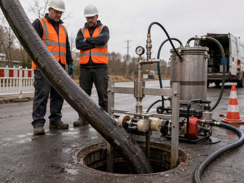
Inversion turns the tube inside out as water or air pressure drives it along the bore, so it rolls against the host wall as it advances; pull-in winches the tube through and then inflates it. ASTM F1216 covers the inversion and cure route, while ASTM F1743 is its pull-in and inflate counterpart, and a single municipal specification often cites both alongside ASTM D5813.
Positioning is checked at both ends: the tube must reach the far manhole fully and stay anchored. This is where a mis-measured length or a snag shows up, and where experienced crews have a real advantage.
Steps 8 to 10: Expansion, Curing and Controlled Cool-Down
Step 8: Expansion and end sealing
The tube is pressurized so it presses evenly against the host wall, and the ends are sealed. Holding the liner tight during cure prevents folds and gaps forming behind the new pipe; the pressure is recorded and the end seals are photographed.
Step 9: Curing by hot water, steam, UV light or ambient
CIPP curing uses four field methods: hot water, steam, UV light and ambient. Published descriptions put UV light fastest, with one equipment maker describing a UV light train curing at about one minute per meter of liner. Steam and hot water typically take about one to four hours, and ambient cure takes longest. A cure log is kept per liner, recording the temperature, time and pressure the resin actually saw.
Hot-water curing releases styrene into the cure water, so handling that water is part of the site plan. NASSCO’s styrene guidance recommends a 15-foot perimeter around emission points and exhaust stacks a minimum of 6 feet above ground, and UV curing reduces odor emission where odor is the binding constraint.
| Curing method | Typical duration | Strengths | When it fits |
|---|---|---|---|
| Hot water | About one to four hours | Even heat transfer and a well-understood cure; water carries heat around bends and into non-circular shapes | Gravity sewers and irregular hosts where speed is not critical; cure water has to be handled. |
| Steam | About one to four hours | Faster heat-up than water, and far less weight sitting in the line | Mains where supplying and removing large volumes of water is difficult. |
| UV light | About one minute per meter of liner | Very fast and consistent cure front, with lower odor emission | Straight runs using a matched UV tube and resin system and the correct UV equipment. |
| Ambient | The longest of the four | Needs no heat source or UV train and no cure water | Short, small-diameter liners and localized work where no heat source is available. |
Step 10: Controlled cool-down
The cured composite and the host pipe expand and contract at different rates as the liner cools. A gradual cool-down lets the liner settle against the host wall and take up its final dimensions without the shrinkage stress a fast temperature drop can introduce. Rushing it can leave a pipe that is cured but stressed.
Steps 11 and 12: End Trimming and Lateral Reconnection
Step 11: End trimming at manholes
Once the liner has cooled, the ends are cut back flush at each manhole. A flush trim opens the bore, removes folded material and leaves a clean transition for the next pipe length or the manhole structure.
Step 12: Reopening laterals with a robotic cutter
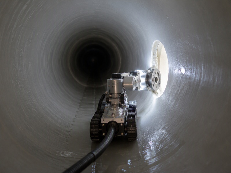
Lining a sewer closes every lateral that enters it, so each one has to be cut open again. A robotic cutter travels the new pipe and reopens each connection to its recorded clock position and diameter, calibrated against the pre-lining survey: the clock position and chainage logged in step 1 tell the operator where to index the robot, and the lateral’s recorded size tells the crew which cutter head to run.
A camera on the cutting head and a follow-up survey confirm the lateral is open, round and free of protruding liner. In our bid reviews, service reinstatement is one of the items most likely to be omitted by a contractor focused only on the main line.
Steps 13 and 14: Post-Installation CCTV and Close-Out
Step 13: Post-installation CCTV and acceptance
The post-installation survey answers one question with evidence: how does CIPP lining work in practice? A camera travels the finished liner, and the result is compared against the pre-installation survey and the specification. Reviewers look for wrinkles and folds above the permitted limit, dry spots, and missed or partly reopened laterals.
Step 14: Close-out records
A completed job leaves a data pack, not just a renewed pipe: survey video before and after, the wet-out log, the cure log with its temperature and pressure curves, the reinstatement record, and retained-sample test results. The IKT institute describes the minimum testing scope as centering on a three-point bending test to determine modulus of elasticity and bending stress.
What Limits Does the CIPP Process Have, and When Is It the Wrong Answer?
How does CIPP lining work in a normal job? The steps above answer that. The limits below show where the method stops.
It keeps the grade it finds. Lining reproduces the existing line and level, so it suits a correctly draining sewer; a back-graded line needs a separate repair.
It reduces the bore. The liner occupies roughly its own wall thickness plus any annular gap the design assumes, so flow capacity has to be checked against the new internal diameter.
It suits a host that still holds its basic shape. Where the pipe is collapsed, severely deformed or missing a section, the line is a replacement job. Reported plumbing-code language discussed in the trade press also limits CIPP where the existing piping is compromised.
Odor and styrene are real site issues. They are managed with a work perimeter and stack heights under NASSCO guidance, or by moving to UV curing. Preliminary 2024 measurements reported that non-styrene polyester resins did not exceed OSHA or EPA exposure limits, but that research is preliminary and not a general clearance.
Very large pipes need access excavation. Published commentary notes that on 72–96 in. pipes, access alone often calls for excavation, so treat access excavation as part of the trenchless scope.
Frequently Asked Questions About CIPP Lining
How does CIPP lining work on a live sewer?
A temporary diversion and service isolation carry the flow while the liner is installed. Flow is routed around the liner section, and each house service is plugged or isolated before the tube goes in. Once the liner is cured and the laterals are reopened, normal flow is restored.
How does CIPP lining work without a full excavation?
The liner enters through existing manholes. The pipe between two access points is renewed with no open trench along its length. Access still has to be opened at manholes and at each service location, so trenchless is not the same as excavation-free.
How much does CIPP lining reduce the pipe diameter?
Roughly the liner wall thickness, plus any annular gap the design assumes. Flow capacity has to be checked against the new bore rather than assumed from the old one, and that check belongs in the design, not after installation.
How long does a CIPP installation take?
It depends on length, diameter and cure method. One equipment maker describes UV light curing at about one minute per meter of liner, while steam and hot water typically take about one to four hours and ambient cure takes longest.
Why is cool-down controlled after curing?
The cured composite and the host pipe cool at different rates. A gradual cool-down lets the liner settle against the host wall without the shrinkage stress that a fast temperature drop can introduce.
When is CIPP the wrong method?
When the host pipe no longer holds its basic shape. A collapsed, severely deformed or missing section is not a lining job, and that line has to be replaced rather than renewed.
Key Takeaways
- Fourteen steps, one order. How does CIPP lining work? The answer is a fixed sequence that starts at a condition survey and ends only when every lateral is reopened and the finished liner is surveyed.
- The survey drives the design. Wall thickness is designed under ASTM F1216 for a partially or fully deteriorated host, as the owner specifies.
- Pot life, not resin volume, is the wet-out risk. Resin has to stay workable long enough to install the whole liner.
- Cure choice follows the site, not the clock. UV is fastest, but it needs a matched tube and resin system.
- Records are the product. Survey video, wet-out and cure logs, retained samples and a final video are what prove the renewal.
- It has limits. Grade, bore, host shape and access all come from the survey, so they are settled before a liner is ordered.
How JSW Delivers the CIPP Process From Survey to Close-Out
JSW is a pipeline engineering and construction company that executes trenchless rehabilitation with its own crews and equipment. Our scope covers pipe restoration solutions, inserted hose lining, pipeline repair services and trenchless technologies.
We keep the process auditable end to end: survey video before and after, wet-out and cure logs for every liner, retained samples and a close-out data pack at handover. The NASSCO CIPP installation performance specification guideline expects key personnel in survey, impregnation, lining and robotic reconnection to carry documented experience, and cites three years of cumulative experience in pipe of similar size and configuration.
- Integrated delivery: survey, cleaning, bypass, lining and reinstatement delivered by one team, with one set of records.
- Auditable process data: CCTV before and after, wet-out and cure logs, and retained samples for testing.
- Design under published standards: thickness designed under ASTM F1216 for the host condition the owner specifies.
- Risk-explicit scope: bypass needs, service isolation and reinstatement priced as line items rather than hidden in a lump sum.
Planning a CIPP renewal and want a step-by-step review of your line? Send your pipe size, material and the latest CCTV survey for a free technical review. Our engineers respond with a scoped recommendation and budget range.





































 English
  Arabic
  Russian
  Spanish
  French
  Vietnamese
  Polish
  Thai
Thai  Indonesian
  Turkish
  Portuguese