
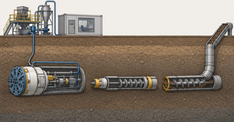
Slurry microtunneling, pilot tube microtunneling and auger microtunneling are the three system families used for remotely operated, non-man-entry pipe jacking. They differ in three places: how each supports the face, how the drive is guided, and how spoil leaves the drive.
Slurry microtunneling closes and pressurizes the face with a bentonite slurry; pilot tube systems establish line and grade first with a guided pilot bore before the cased augers and product pipe follow; auger machines cut an open face and convey spoil with a cased screw conveyor. This comparison tests all three systems against the three constraints that decide most drives: alignment accuracy, ground range and achievable drive length. Every recommendation in this comparison is conditional on ground, diameter, depth and tolerance requirements, and no system is universally the right answer.
What Are the Three Microtunneling Systems?
Microtunneling is a pipe jacking method in which the machine is controlled from the surface, the operator is never inside the bore, and the jacked pipe forms the final lining. Published descriptions place the technique at roughly 0.35–4 m (about 14 in to 13 ft) in diameter, and note that the diameter is too small for a person to drive the machine, so it is remotely operated. ASCE/CI 36-15, Standard Design and Construction Guidelines for Microtunneling (April 2015), is explicit that microtunneling describes a method and does not impose size limitations on diameter. That position from ASCE/CI 36-15 is why the “micro” boundary is a market convention rather than a hard rule.
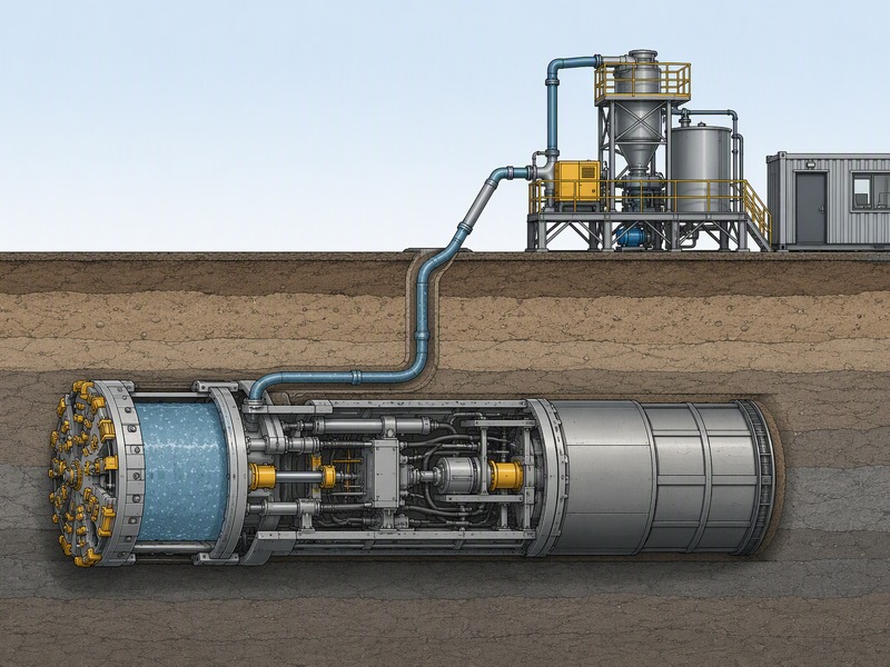
- Slurry microtunneling (slurry shield). The machine is closed-face and pressure-balanced: a bentonite slurry pressurizes the plenum behind the cutterhead to hold the face and the groundwater, spoil travels to the surface in the slurry return line, and a separation plant cleans the slurry so it can be recirculated. With a crushing head it can work in rock as well as soft ground, which gives slurry microtunneling the widest ground range of the three systems.
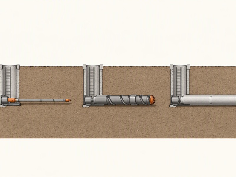
- Pilot tube microtunneling (guided boring). A pilot tube is installed first on line and grade; cased augers are then advanced from the launch shaft while the pilot tubes are pushed out into the reception shaft; the product pipe is then thrust through, or a powered cutting head or power reaming head upsizes the bore to match a larger product pipe, up to 48-inch flush-wall jacking pipe.
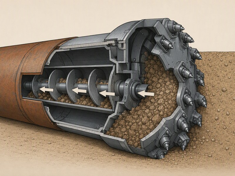
- Auger microtunneling. An open-face cutting head feeds spoil into a cased screw conveyor that runs back through the jacked casing to the launch shaft. There is no continuous face support, so the face has to stand on its own; that makes auger microtunneling simple and economical in dry, stable ground and unsuitable where the face will not stand.
Pipe Jacking Association guidance groups microtunneling machines into two types, pressurized slurry and auger, both with face support capability, fully guided and remotely controlled from the surface with man entry generally not required. earth pressure balance (EPB) machines are described as serving larger pipe jacks and best in cohesive soils, conditioned with bentonite, water or polymer in mixed faces. Pilot tube systems are a guided variant that trades the slurry plant for a tighter, stepwise alignment.
How Does Each System Handle the Three Decisive Constraints?
Most system arguments reduce to alignment accuracy, ground range and drive length. Spoil handling, shaft size and cost follow from those three. The sections below take each constraint in turn, then consolidate them in Table 2.
Alignment accuracy
Pilot tube systems are quoted at the tightest accuracy of the three: within about ±1 inch (25 mm) from design grade and ±3 inches (75 mm) from design alignment at any location. The pilot tube is installed first and held on line and grade, and every later stage follows the same corridor, so error accumulates little. Slurry and auger machines steer with continuous guidance – laser target, water leveling or gyro and inertial systems in deep or curved drives – and PJA guidance gives a typical tolerance of ±50 mm of true line and level at any point in stable, self-supporting, homogeneous ground.
The published accuracy applies to stable, self-supporting ground; in unstable ground or where obstructions occur a tighter tolerance cannot be assumed, and a larger pipe size may be needed to achieve one. On drives we have supported, gravity sewer drives are where accurate grade really matters, because the pipe is the flow channel and grade cannot be corrected after the fact.
Ground range
Slurry microtunneling covers the widest range. Because the face is pressure-balanced, it can hold saturated sands, silts, mixed ground and, with a crushing head, rock.
Pilot tube microtunneling is most suitable in displaceable soils with shallow water levels or low permeability soils, where the pilot tube can displace or cut without a pressurized face. Auger microtunneling needs dry, stable ground that will stand at an open face without continuous face support. Depth, like ground, sets the envelope: the deepest shaft usually governs, not the drive itself.
Achievable drive length
Drive length is a function of diameter, ground, friction and how hard the jacks can push. PJA publishes indicative jacking lengths between shafts by nominal internal lining diameter (Table 1), and notes that lengths can considerably exceed 1 km depending on diameter, ground and excavation method – but only after project-specific risk analysis. Pilot tube microtunneling typically works in shorter drives: published guidance puts typical lengths at about 400 ft (roughly 120 m) or less, with longer drives achieved. Auger drive length is governed by face stability and screw-conveying distance, so auger microtunneling generally runs shorter than a slurry shield.
| Nominal internal lining diameter | Indicative jacking length between shafts |
|---|---|
| Below 0.9 m | About 150 m |
| 1.0 m | About 250 m |
| 1.2 m | About 450 m |
| 1.5 m | About 700 m |
| 1.8 m | About 900 m |
| 2.4 m | About 2,000 m |
| Attribute | Slurry (slurry shield) | Pilot tube (guided boring) | Auger |
|---|---|---|---|
| Face condition | Closed, pressure-balanced with bentonite slurry | Guided pilot bore, then cased augers | Open face, no continuous support |
| Face support | Positive and active | Passive or displacement in suitable soils | None continuous |
| Ground range | Widest: soft ground, mixed ground and rock with a crushing head | Displaceable soils, shallow water table or low permeability soils | Dry, stable ground only |
| Alignment accuracy | Continuous guidance; PJA typical ±50 mm in favorable ground | Tightest quoted: about ±1 in grade, ±3 in alignment | Continuous guidance, comparable to slurry in suitable ground |
| Typical drive length | Long; can exceed 1 km at larger diameters after risk analysis | About 400 ft (roughly 120 m) or less typical, longer achieved | Generally shorter than a slurry shield |
| Spoil handling | Slurry return line plus a separation plant | Cased augers, spoil usually drier | Cased screw conveyor, dry spoil |
| Shaft footprint | Largest; machine, separation and control footprint | Small; shafts typically 8–16 ft (about 2.4–4.9 m) | Small to moderate |
| Cost structure | Highest unit cost: machine, separation plant and wet spoil management | Moderate; competitive at small diameters and short drives | Lowest unit cost in suitable ground |
| Risk / limitation | Slurry loss, separation and disposal, larger site and higher mobilization | Ground-dependent; not for rock or unstable saturated faces | Face collapse and settlement risk; dry stable ground only |
Spoil Handling, Shaft Footprint and Site Logistics
Spoil handling is often what decides between systems on an urban site. A slurry shield produces a slurry return that must be separated at the surface: the separation plant, slurry tanks and handling area are part of the working site, and spoil is managed as wet material. Pilot tube and auger systems convey spoil mechanically with cased augers, so the surface plant is simpler and the spoil is usually drier and easier to load out. The difference between a wet slurry return and a dry screw conveyor often matters more than the machine itself when the launch site is tight.
Shaft footprint follows the same logic. Precast caisson shafts of 2.4–4 m diameter are described as suitable for microtunneling, and PJA shaft tables cover dry ground to about 15 m with sheet piling and about 20 m with secant piling.
Pilot tube shafts are typically small – about 8–16 ft (roughly 2.4–4.9 m). One published comparison notes microtunneling access doors larger than 60 inches (about 1.5 m) and an average minimum staging area of about 11,000 sq ft (about 1,000 m²), so even a “small” trenchless site is not a zero-footprint site. In our bid reviews, the deciding question is frequently not which machine cuts the ground, but which one fits the available launch area together with its plant.
What Drives the Cost Structure of Each System?
One widely circulated case-study deck prices microtunneling per inch of diameter at about USD 55–95 per foot; these are published ranges, not quotations. A large municipal cost-criteria memorandum prices it per linear foot at about USD 35–75; these are published ranges, not quotations. The two are not directly comparable.
Diameter, ground, depth, shaft cost and mobile plant move the number most. Within that envelope the ranking is consistent: auger is the lowest unit cost where an open face suits the ground, pilot tube is moderate at small diameters and short drives, and the slurry shield is highest because of its separation plant and wet spoil handling.
Cost is not only the machine rate. Shafts, mobilization, spoil disposal and the risk of a stalled drive all enter the tender. A longer drive with fewer shafts can reduce total shaft cost, so a slurry shield that can reach farther can win on total cost even at a higher unit rate. We have seen bids turn on this: the cheaper machine rate loses once the extra shaft and the disposal cost are priced in.
Which System Fits Which Ground?
Ground condition is the first filter, before accuracy or cost. Table 3 maps common ground types to the system that usually fits and the reason why.
| Ground condition | System that usually fits | لماذا |
|---|---|---|
| Dry, stable cohesive soil or clay | Auger (or slurry if the drive is long) | An open face stands without continuous support |
| Saturated sand and silt below the water table | Slurry shield | Active slurry pressure balances groundwater at the face |
| Mixed ground with cobbles or boulders | Slurry shield with crush capability | A closed face and crushing head handle variable material |
| Rock | Slurry shield with a crushing head | A slurry shield can cut and hold the face in rock |
| Displaceable soils, shallow water table or low permeability soils | Pilot tube (guided boring) | A pilot tube can be installed on line and grade in these soils |
| Small diameter, tight tolerance, short drive | Pilot tube | Tightest quoted accuracy and compact shafts |
| Unstable, running or open-grained ground with no water control | Slurry shield (closed face) | An open face cannot hold this ground; a closed face with slurry pressure is required. |
Selection Decision Logic: Choose Slurry When, Choose Pilot Tube When, Choose Auger When
Turning the tables into a decision is straightforward if the constraints are ranked honestly.
- Choose slurry microtunneling when the face is below the water table, the ground is mixed or rocky, the drive is long, or the ground cannot be controlled at an open face. The price is a larger site and a separation plant.
- Choose pilot tube microtunneling when line and grade are critical, the diameter is small, the drive is relatively short, and the ground is displaceable or of low permeability. The tightest quoted accuracy is its main advantage.
- Choose auger microtunneling when the ground is dry and stable, the drive is short, tolerance is normal, and cost is the priority. Auger microtunneling applies only where the face can stand on its own; in running or water-bearing ground the drive needs a closed face.
If more than one system fits, the tie-breakers are site footprint, spoil disposal and total cost across the whole drive – not the machine rate alone.
Honest Counter-Arguments and the Method-Not-Machine Rule
The honest counter-arguments are worth stating. A slurry shield earns its separation plant below the water table, in mixed or rocky ground and on long drives; in dry, stable ground the plant and wet spoil handling are avoidable cost. Pilot tube microtunneling holds its tightest tolerance in displaceable, low-permeability soils; in rock or at a high water table, slurry is the system that fits. Auger microtunneling returns the lowest unit rate while the face stands; where the ground will not stand, recovering a collapsed face costs more than the saving.
ASCE/CI 36-15 treats microtunneling as a method rather than a machine type, and that framing is the practical one. The method is remote control, guidance, pipe jacking as the lining and a face that is managed; slurry, pilot tube and auger are three ways of delivering it. Pipe Jacking Association guidance supports the same view: standard jacking pipe diameters generally range from 150 mm to 2,400 mm, or greater when required.
Choosing a system is therefore choosing the excavation and support approach that matches the ground, not choosing whether the work counts as microtunneling. Our field teams record the choice as a risk decision: which system leaves the least face and settlement risk for the ground actually expected.
الأسئلة الشائعة
What is the difference between slurry, pilot tube and auger microtunneling?
Slurry, pilot tube and auger microtunneling differ in face support, drive guidance and spoil removal. Slurry microtunneling uses a closed, pressure-balanced face with a bentonite slurry and a separation plant; pilot tube microtunneling installs a pilot tube on line and grade first, then cased augers, then the product pipe; auger microtunneling cuts an open face and conveys spoil with a cased screw conveyor and needs dry, stable ground.
Which microtunneling system is the most accurate?
Pilot tube microtunneling is quoted at the tightest accuracy of the three. Published figures put it within about ±1 inch (25 mm) from design grade and ±3 inches (75 mm) from design alignment at any location. Slurry and auger machines use continuous guidance and are typically held to about ±50 mm of line and level in stable, homogeneous ground.
Can auger microtunneling work below the water table?
Auger microtunneling suits dry, stable ground; below the water table, in running sand or in mixed ground, a closed-face slurry shield is required because an open face cannot hold the ground.
Is slurry microtunneling more expensive than auger microtunneling?
Usually, at the unit rate. Slurry microtunneling brings a machine, a separation plant and wet spoil management to site, so its unit cost is typically the highest of the three. For a 90 m drive in dry, stable ground with a tight budget, auger microtunneling is the intended first choice rather than a compromise.
How long a drive can each system complete?
Drive length depends on diameter, ground, friction and jacking capacity. Pilot tube microtunneling typically works at about 400 ft (roughly 120 m) or less, with longer drives achieved. Auger microtunneling is generally shorter than a slurry shield. Slurry microtunneling can reach the longest drives; PJA indicative lengths rise to about 2,000 m at 2.4 m diameter, and lengths can considerably exceed 1 km, but only after project-specific risk analysis.
Does ASCE/CI 36-15 define microtunneling by machine type?
ASCE/CI 36-15 treats microtunneling as a method rather than a machine type. ASCE/CI 36-15 states that microtunneling describes a method and does not impose size limitations on diameter. That method-based framing is why all three systems belong to one family.
My Ground Is Mixed Clay and Sand 6 m Below the Water Table – Which System Fits?
A closed pressure-balanced slurry shield fits this ground: the drive sits below the water table, the face cannot stand unsupported, and a crushing head covers mixed material.
النقاط الرئيسية
- Slurry microtunneling covers the widest ground range because its closed, pressure-balanced face holds groundwater and, with a crushing head, rock.
- Pilot tube microtunneling is quoted at the tightest accuracy and suits displaceable or low-permeability soils, small diameters and shorter drives.
- Auger microtunneling is the simplest and usually the lowest unit cost, but only in dry, stable ground with no need for continuous face support.
- The three decisive constraints are alignment accuracy, ground range and achievable drive length; spoil handling, shaft footprint and cost follow from them.
- ASCE/CI 36-15 treats microtunneling as a method, not a machine type, so system choice is a ground-and-risk decision.
- If more than one system fits, compare total cost across the whole drive – shafts, disposal and risk included – not the machine rate alone.
How JSW Supports Microtunneling System Selection
JSW is a pipeline engineering and construction company that executes trenchless crossings with its own crews and equipment. Our scope covers microtunneling construction, trenchless technologies, horizontal directional drilling services, خدمات تركيب خطوط الأنابيب و pipeline inspection services.
We select and run the system that matches the ground rather than the one that is easiest to mobilize. JSW installs pipelines from DN300 to DN1500 (12–60 inches) by microtunneling, with single drives up to 600 m, laser guidance accuracy of about ±25 mm using a VMT laser guidance system, and installation depths of about 2–25 m. Ground capability runs from soft clay and sand through cobbles and mixed ground to hard rock up to about 80 MPa UCS, with interjack stations deployed roughly every 100–150 m for extended drives.
- Ground-led selection: we match slurry, pilot tube or auger to the geotechnical model rather than to a default.
- Auditable process data: guidance, jacking force and alignment records are kept through the drive.
- Risk-explicit pricing: shaft count, spoil disposal and ground risk are priced openly rather than buried.
- Safety and compliance: JSW holds ISO 9001:2015, ISO 14001:2015 and ISO 45001:2018 certification.
Tell us your ground profile, diameter and drive length, and we will match the system to those constraints. Send your ground investigation and tolerance for a free technical review; our engineers respond with a scoped recommendation and budget range.





































 English
  Arabic
  Russian
  Spanish
  French
  Vietnamese
  Polish
  Thai
Thai  Indonesian
  Turkish
  Portuguese