
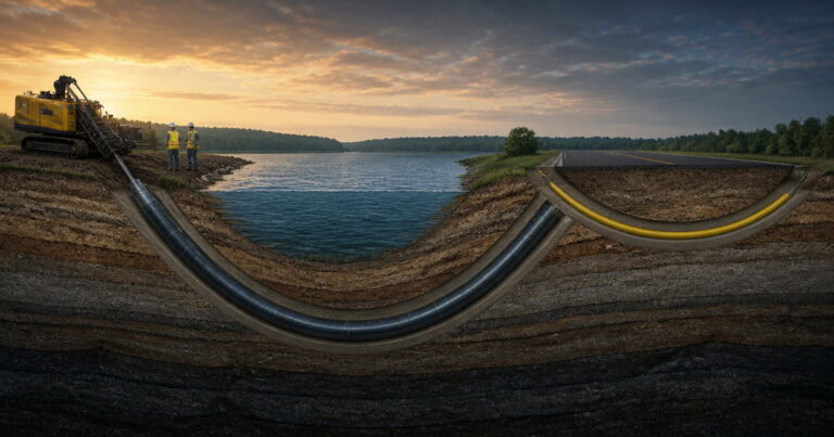
Trenchless construction for gas pipelines is the practice of installing or renewing gas mains and transmission lines below ground without a continuous open trench, and horizontal directional drilling (HDD) fits it wherever a long or curved crossing must carry a pressure line. Which method fits which gas job is decided by the gas itself: high-pressure steel transmission mains designed to ASME B31.8 and welded to API 1104 expectations need one method family, while medium- and low-pressure polyethylene distribution mains joined by heat fusion and controlled by squeeze-off need another.
In our bid reviews, trenchless gas pipeline installation is a method-fit decision before it is a geology decision. Steel transmission mains designed to ASME B31.8 and welded to API 1104 expectations pull well into a curved bore but are stiff. Polyethylene distribution mains joined by heat fusion follow the bore curve easily and are controlled by squeeze-off practice.

Why the Gas System Split Decides the Method Before Geology Does
Gas is not one product with one pipe. Pressure class and material each carry their own design code and joining method, and those rules eliminate trenchless options before a geotechnical report is opened. The first question is what the line is, not what the ground is:
- Transmission or distribution.
- Steel or polyethylene.
- Which code governs.
Steel transmission mains follow ASME B31.8 and API 1104 weld quality
Transmission mains are the long, high-pressure lines that move gas between regions and into cities. They are almost always steel, designed to ASME B31.8 (Gas Transmission and Distribution Piping Systems) and joined by girth welds made and inspected to API 1104. A welded string pulls well but is stiff: it needs a generous bend radius in a curved bore, and every joint must be coated and, where required, cathodically protected.
PE gas distribution mains follow fusion joining and squeeze-off practice
Distribution mains and services feed streets, buildings and meters, usually at medium or low pressure and increasingly in polyethylene (PE), which now dominates new gas distribution work. Joints are heat fused rather than welded, qualified to ASTM F2620 for butt fusion and ASTM F1055 for electrofusion, and controlled by squeeze-off practice guided by ASTM F1041. PE follows a bore curve, so what matters is minimum bend radius, pull tension and the fusion joints themselves.
Trenchless Construction for Gas Pipelines: The Method-Fit Map
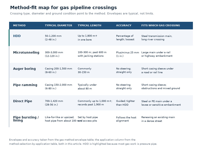
Trenchless construction for gas pipelines draws on one family of methods, each earning its place on a different part of the gas system. Ground, diameter, accuracy and live gas decide which method survives to be priced.
HDD: long, curved crossings for steel or PE pressure lines
Horizontal directional drilling drills a steerable pilot bore along a controlled arc, reams it to about 1.2 to 1.5 times pipe outside diameter, and pulls the pipe back through the fluid-filled bore. Typical diameters reach 1,200 mm (48 in.) and single bores 1,800 m and beyond. It fits the long single-span road, rail or river crossing, but not gravity flow.
Microtunneling: short to medium straight drives, large diameter, tight line and grade
Microtunneling pushes a guided pipe from a launch shaft behind a remotely operated machine with a closed, pressurised face. Routine diameters are 300 mm to 3,000 mm (12 in. to 120 in.) and drives 100 m to 300 m. It holds line and grade to about ±25 mm (1 in.), suiting precise or settlement-sensitive large-diameter crossings.
Auger boring and pipe ramming: casing installation over short crossings
Auger boring and pipe ramming install a steel casing, usually as a sleeve for a carrier main. Auger boring cuts a straight, constant-grade bore with an auger that conveys spoil to the drive pit; pipe ramming drives the casing with a percussive hammer. Both are casing-first methods with no ability to steer, so the line cannot be corrected mid-drive.
Direct Pipe: single-pass installation of a prepared pipe string
Direct Pipe blends the two families: a surface-launched, HDD-style rig pushes a face-supported cutting head with a pipe thruster and installs the line pipe in one pass, with no separate reaming and pullback. Applied at roughly 700 mm to 1,420 mm (28 in. to 56 in.) over drives reaching 2,000 m, it fits long, sensitive crossings.
Pipe bursting, slip lining and cured-in-place lining: renewing existing mains
The renewal methods work on a main that already exists. Pipe bursting pulls an expander through the old pipe and draws a new one behind it; slip lining inserts a new pipe inside the old one, following ASTM F585; and cured-in-place lining, covered by ASTM F1216, forms a new wall inside the host pipe. All change capacity or rely on the host pipe.
| الطريقة | Typical diameter | Typical length | Accuracy | Suitable ground | Main limitation |
|---|---|---|---|---|---|
| محرك الأقراص الصلبة | 50–1,200 mm (2–48 in.) | Up to 1,800 m+ in one bore | Percentage of length; loosest | Most soils and soft to medium rock | No gravity flow; poor in gravel and cobbles; inadvertent return risk |
| النفق الدقيق | 300–3,000 mm (12–120 in.) | 100–300 m; past 600 m with jacking stations | ±25 mm (1 in.) | Soft, loose or saturated soil; rock | Launch and reception shafts; boulders and mixed ground |
| Auger boring | Casing 200–1,500 mm (8–60 in.) | Commonly 30–150 m | No steering; straight only | Consistent soil; mixed ground with spoil removal | No steerability; boulders over one third of casing diameter |
| Pipe ramming | Casing 150–2,000 mm (6–80 in.) | Typically under about 80 m | No steering; straight only | Mixed ground, obstructions, road and rail crossings | No navigation; casing only, carrier pipe installed separately |
| الأنبوب المباشر | 700–1,420 mm (28–56 in.) | Commonly up to 1,000 m+; records past 1,900 m | Guided; tighter than HDD | Most conditions, including gravel and rock | Large launch setup; cover limited by sealing envelope |
| Pipe bursting / lining | Like-for-like or upsized; host pipe from about 100 mm | Set by host pipe and access pits | Follows the host alignment | Replacement or renewal in most soils | Reduces diameter or relies on host pipe; changes capacity and pressure rating |
Method Selection by Gas Application
The fastest way to select a method is to name the gas application, because it already carries the diameter, the pressure class and the accuracy needed. Trenchless gas pipeline installation is a fit problem first and a price problem second.
| Gas application | Likely method | Risk or limitation to resolve |
|---|---|---|
| Steel transmission main, long river crossing | HDD; Direct Pipe as alternative | Inadvertent return; pullback load and coating damage; bend radius; scour cover |
| Large main under a rail or highway embankment | Microtunneling, often with casing | Shaft cost premium; settlement monitoring; boulders |
| Short casing sleeve under a road or rail line | Auger boring or pipe ramming | No steerability once started; boulders over one third of casing diameter |
| Steel or PE main under a levee or sensitive embankment | الأنبوب المباشر | Launch setup size; cover limited by sealing envelope |
| PE main replacement in a dense street | Pipe bursting, slip lining or cured-in-place lining | Change of diameter and capacity; adjacent services; live-gas isolation |
| New PE main along a street with mature trees | HDD (small to midi rig) | Minimum bend radius; fusion joint integrity; separation |
| Live gas distribution tie-in | HDD to the tie-in, then hot tapping or squeeze-off | Flame and hot-work control; purge and inerting; pressure control before any weld |
Gas-Specific Constraints That Change the Job
How does the transmission versus distribution split change method selection?
Every method above also installs water and telecom pipe, so the method alone is not what makes gas unique.
Cover and separation: the code fixes the profile before you drill
Depth of cover and clearance to other utilities are design inputs, not site decisions. Under ASME B31.8 and the corresponding US federal cover rules, published minimum cover commonly works out at about 30 in (0.76 m) in normal soil and 36 in (0.91 m) under roads, railroads and drainage ditches. US federal rules also require at least 12 in. (305 mm) of clearance from other underground structures for transmission lines.
No open flame near live gas: isolation, purge and tie-in
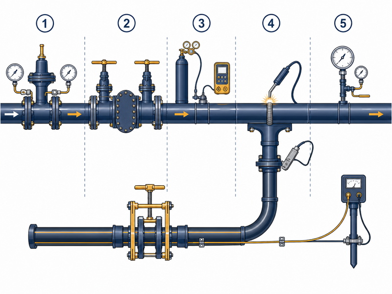
A crossing usually connects to a live system at each end, where gas work diverges most from water or telecom. The safe sequence is pressure control, isolation, purge and inerting of the section, and only then any welding or hot work. Live-line welding or hot tapping follows API RP 2201, and NFPA 54 sets the surrounding safety expectations.
Ground movement and settlement beside a live main
Move the ground beside a live gas main and the main moves with it; move the main and you load a joint, and a loaded joint on an ageing main is where leaks start. Settlement control therefore sits inside the gas scope.
Coating and cathodic protection through a bore
A steel main arrives at the crossing coated and, in most designs, cathodically protected. Pulling it through a bore is where that protection is most at risk: the coating must survive abrasion from the bore and from reamed cuttings and leave without holidays that would start corrosion where no one can inspect it.
Leak detection and monitoring
A bore beside live gas needs continuous atmospheric monitoring during construction and a documented leak check at completion.
Weld and fusion quality: steel NDT versus PE fusion qualification
The quality regime splits with the material. On steel transmission lines, girth welds are made and inspected to API 1104, with visual inspection and non-destructive testing (radiography or ultrasonic), and the string is normally pressure-tested before installation.
On PE mains the equivalent controls are fusion procedure and joiner qualification built around ASTM F2620 and ASTM F1055. We have found that, with no weld to image, quality is proven by procedure, calibration and records. An unqualified fusion operator can be the whole risk.
| Constraint | Control |
|---|---|
| Minimum depth of cover | Profile below the code minimum for the full crossing; class location and casing set at design |
| Separation from other utilities | Survey and locates before drilling; at least 12 in. (305 mm) for transmission lines |
| Open flame and hot work near live gas | Pressure control, isolation, purge and inerting before welding; live-line work per API RP 2201 |
| Ground movement beside a live main | Face-supported methods where settlement is critical; trigger levels and a stop-work procedure |
| Coating and cathodic protection | Abrasion-resistant coating; controlled pull force; electrical testing after pullback; CP test stations and tracer wire |
| Leak detection and monitoring | Continuous methane monitoring; purge and pressure test at completion; as-built records |
| Weld and fusion quality | API 1104 welds with NDT for steel; ASTM F2620 and ASTM F1055 fusion for PE |
Where HDD Fits, and Where It Does Not
Which gas pipeline jobs are unsuitable for a trenchless crossing?
HDD sits at the centre of trenchless construction for gas pipelines, but it has edges. On crossings we have supported, HDD fits when the line is a pressure line, when one curved span beats a shaft, and when the pipe can tolerate the bore curve and the pull. It does not fit:
- Gravity flow, which needs a constant fall a curved bore cannot hold.
- Large diameters above roughly 1,200 mm.
It is also a poor choice in loose gravel, cobbles and shallow permeable ground.
Hydrogen and Repurposing: New Questions for Old Mains
The gas system is changing at the same time as the construction methods, and hydrogen is why. It raises three questions a natural gas design does not:
- What the material does in hydrogen service.
- What the welds do.
- How much hydrogen permeates through the pipe.
For a steel main, design may move from ASME B31.8 towards ASME B31.12, whose material and weld requirements are more stringent, and higher-strength steels come under review for hydrogen embrittlement. For PE mains the issue is permeation, because hydrogen passes through polyethylene more readily than methane. Pilot projects in the United Kingdom and Europe have run blends of around 20 percent hydrogen by volume through existing steel and PE networks without changing the method.
A Scoping Decision List for a Gas Trenchless Crossing
Selection becomes reliable when the same questions are asked every time.
- Classify the line. Transmission or distribution, steel or PE, operating pressure and governing code (ASME B31.8; ASME B31.12 for hydrogen).
- Confirm the design profile and target. Required cover, class location, scour allowance, casing, pipe diameter and the line-and-grade tolerance needed.
- Prove separation. Utility locates and survey sufficient to show the required clearance along the whole bore, before drilling.
- Read the geotechnical report against the methods. Soil and rock type, groundwater, and gravel, cobbles or boulders, run against Table 1.
- Define the gas and integrity controls. Isolation, purge and inerting, coating for pullback, cathodic protection, weld and fusion standards, NDT records and the pressure test.
- Set monitoring and contingency. Settlement monitoring with trigger levels, inadvertent return response and a stop-work procedure.
Scope of Application: Gas Jobs That Suit a Trenchless Crossing
A trenchless crossing suits gas work where the line is a pressure line, the obstruction cannot be opened, and the pipe can tolerate a curved installation path.
- In scope: river, road and rail crossings, live-main replacement, and renewal inside an existing main.
- Out of scope: short service connections and shallow domestic work, where open trench is standard practice.
- Out of scope: gravity-flow systems, which are not part of a pressurised gas network.
How This Changes by Project Role
What governs a distribution network engineer choosing a trenchless method?
Expect a mini or midi rig, fused polyethylene, and squeeze-off control; check the separations and the casing requirements rather than the rock strength.
What governs a transmission pipeline engineer choosing trenchless construction?
Expect wireline or gyro guidance, welded steel to ASME B31.8 and API 1104 expectations, and a crossing priced against a bore plan with hydrostatic testing at the end.
How does hydrogen repurposing change the trenchless construction decision?
Separate the material questions from the construction questions: the trenchless method usually survives a hydrogen blend, while the pipe, welds and permeation checks may not.
النقاط الرئيسية
- Trenchless construction for gas pipelines starts with the gas system, not the ground: steel transmission mains to ASME B31.8 with API 1104 welds need one method family, and PE gas distribution mains joined by fusion and squeeze-off need another.
- HDD leads gas work because most of it is pressure pipe and most crossings are long; it is wrong for gravity flow, loose gravel and cobbles, and diameters above roughly 1,200 mm.
- Microtunneling, auger boring, pipe ramming and Direct Pipe cover the crossings HDD cannot: large diameters, tight alignments, short casing drives and long single-pass installations.
- Cover, separation, purging, coating integrity, cathodic protection and monitoring are gas-specific constraints that must be priced, not discovered on site, and quality splits with the material: API 1104 with NDT for steel, ASTM F2620 and ASTM F1055 fusion for PE.
Frequently Asked Questions About Trenchless Construction for Gas Pipelines
These are the questions engineers and asset owners raise most often when scoping a gas crossing.
Which trenchless method is used most for gas pipelines?
Horizontal directional drilling is the most common trenchless method for gas because most gas work is pressure pipe, and pressure pipe tolerates the curved bore HDD produces.
Can HDD install PE gas distribution pipe under a road?
Yes. Polyethylene mains and services are routinely pulled through an HDD bore because PE follows the bore curve and is light enough to keep pullback tension within its allowable limit. What matters is minimum bend radius, allowable tensile load and the fusion joints that must survive the pull.
How deep must a gas pipeline be buried at a crossing?
Depth of cover is a code question before it is a construction question.
Can trenchless methods renew an existing gas main without digging it up?
Yes. Pipe bursting pulls an expander through the old pipe and draws a new one behind it, while slip lining and cured-in-place lining insert a new wall inside the existing pipe.
Does hydrogen blending change the trenchless method or the pipe?
It changes the engineering questions around the pipe more than the trenchless method itself. Design moves towards ASME B31.12, the hydrogen piping and pipeline code, whose material and weld requirements are more stringent than ASME B31.8, and higher-strength steels, weld quality and permeation through polyethylene all come under review. Demonstration projects have run blends of around 20 percent by volume in existing steel and PE networks.
How JSW Supports Gas Trenchless Crossings
Trenchless construction for gas pipelines is delivered by JSW with our own crews and equipment rather than resold. Our scope covers HDD crossing services, microtunneling construction, pipe fabrication with automatic pipeline welding, pipe restoration solutions, and the خدمات تركيب خطوط الأنابيب that complete the line.
Because we plan, engineer and build the work ourselves, our trenchless gas pipeline installation pricing reflects real site conditions rather than catalogue rates, and we will say when a method is outside its envelope instead of bidding it and managing the risk later. Our field teams price the gas-specific controls as scope, not contingency: purge planning, coating and cathodic protection through the bore, weld and fusion records, and settlement monitoring.
- Integrated delivery: one engineering team from ground investigation and bore design through welding, coating protection, tie-in and pressure testing.
- Auditable process data: weld and fusion records, NDT results, coating test results, pull-force logs and as-built cover records.
- Risk-explicit pricing: inadvertent return, settlement and live-gas isolation priced as line items, not contingency clauses.
- Safety and compliance: hot-work and purge procedures, methane monitoring and trigger levels built into the method statement.
Scoping a gas crossing and not sure which trenchless method fits your application? Send your pipe material and diameter, drive length, crossing type, required depth of cover and geotechnical report for a free technical review. Our engineers match the method to the gas application and return a scoped recommendation.





































 English
  Arabic
  Russian
  Spanish
  French
  Vietnamese
  Polish
  Thai
Thai  Indonesian
  Turkish
  Portuguese