
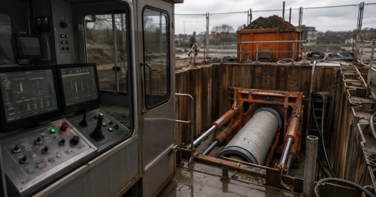
A practical microtunneling definition is four operating rules applied together: remote control from the surface with no man entry, active guidance that holds line and grade, pipe jacking as the lining method, and face support that balances the ground at the cutterhead. A drive that meets all four is microtunneling; a drive that meets three of them is a different method wearing the same name. Together they are the eligibility test a designer applies before a scope is priced or bid. This guide works through each rule, the checkpoints a bid reviewer uses, and where ASCE/CI 36-15 draws the line between method and diameter.
What Is the Practical Definition Used in This Guide?
The microtunneling definition used in this guide is a checklist rather than a label: a drive qualifies when it is unmanned, steered to a stated line and grade, lined by jacked pipe, and excavated behind a supported face. A qualifying drive shows all four together: remote control, guidance, pipe jacking and face support. Where any one is absent, the scope is a different method.
Microtunneling is commonly described as a technique for utility tunnels of roughly 0.35–4 m (about 14 in to 13 ft) in diameter, and the same description notes that the small diameter makes it impossible to have an operator driving the machine, so the machine must be remotely operated. The Pipe Jacking Association adds that standard jacking pipe diameters generally range from 150 mm to 2,400 mm, or greater when required. The published size figures are planning envelopes rather than rules; what qualifies is decided by the four rules that follow.
My Drive Is 1,200 mm and Curved – Do All Four Rules Still Apply?
At 1,200 mm the four rules apply unchanged: the drive is still unmanned, guided, jacked and face-supported, limited only by the pipe’s joint deflection.
Rule 1: Remote Control – Why the Definition Starts With No Man Entry
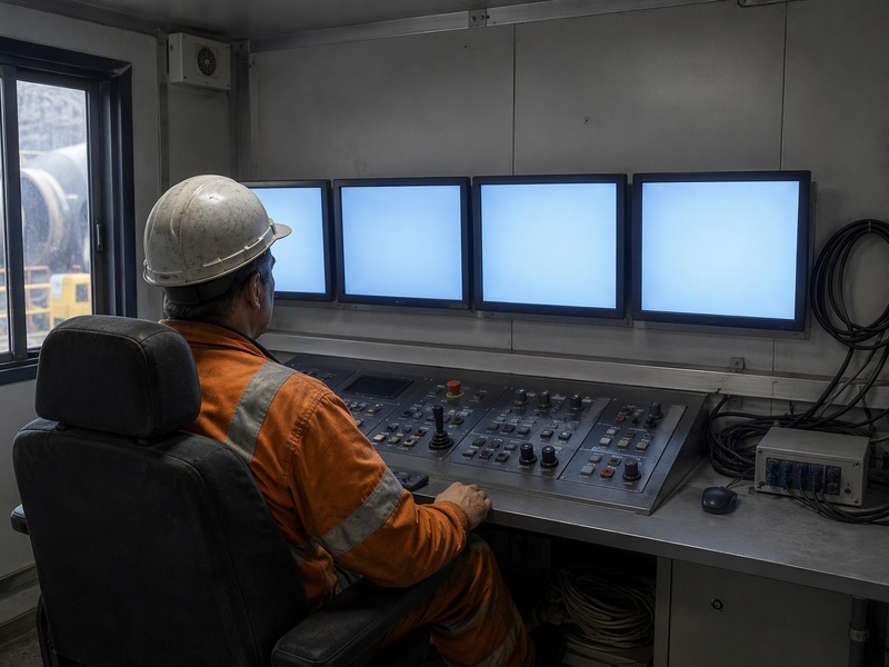
The drive is operated entirely from the surface, so the machine itself stays unmanned. The machine is driven from a surface control cabin, and steering, cutterhead rotation, jacking and spoil or slurry removal are all commanded from it. Remote control is a defining requirement rather than a convenience feature: it is what allows the drive to pass under roads, railways and live services where a manned heading would not be accepted.
What does remote control from a surface cabin actually require?
A control cabin houses the operator interfaces plus the telemetry that ties them to the machine. A drive needs four channels working together: a guidance readout showing where the cutterhead is, a steering command path to the articulation or shield jacks, a jacking-force readout, and a spoil or slurry monitoring loop. A microtunneling machine also carries its own sensors for roll, pitch, cutterhead load and plenum pressure, and those signals reach the cabin as telemetry, not as operator judgment.
Our field teams treat the cabin as the single point of control for the drive; bids that list the control system as an accessory miss a defining requirement.
How Small Does a Drive Have to Be Before Entry Becomes Impossible?
Entry becomes impossible below roughly 900 mm, so face inspection, cutterhead changes and rescue are solved from the surface. The published sizing note is direct: at these diameters it is not possible to have an operator driving the machine, so machines are remotely operated. Cutterhead intervention therefore happens from a shaft, and rescue planning follows OSHA confined-space rules and the UK CDM Regulations rather than the pipe.
Rule 2: Guidance – How the Definition Holds Line and Grade
The second rule is that the drive is actively guided against a design line and grade, not merely aimed. Guidance separates microtunneling from an unsteered drive, and gravity sewers depend on it most, because a sewer that loses grade over a long drive cannot be corrected afterwards.
Laser target, theodolite total station and water leveling
In the routine case a laser is mounted on the line in the launch shaft, a target on the machine reads the beam, and a theodolite total station checks the shaft reference and the as-built alignment.
Water leveling is used where an optical level is impractical or the vertical datum must be carried a long distance, because it does not depend on line of sight.
Pipe Jacking Association guidance gives a typical tolerance of ±50 mm of true line and level at any point in stable, self-supporting, homogeneous ground, and notes that finer tolerances may not be attainable in unstable ground or where obstructions occur. JSW’s own laser-guided microtunneling work is quoted at about ±25 mm. Turning the published figure into a project acceptance tolerance is a design step: guidance accuracy, expected drift and the receiving structure’s tolerance are combined before launch, and the log is checked against that value.
Gyro and inertial guidance in curved or deep drives
Two conditions break an optical reference: a curve that puts the machine out of sight of the launch shaft, and depth that makes a stable sight line hard to hold. There a gyro or inertial guidance unit on the machine tracks heading and attitude and is reconciled with the shaft reference at each check. Curved drives are feasible but constrained: standard 2.5 m pipes can be jacked to a radius of about 200 m, and shorter pipes turn tighter curves within the pipe manufacturer’s permitted joint deflection. The guidance log is the primary grade record for the drive, and a post-breakthrough pipeline inspection service adds an independent geometric check of the installed line.

Rule 3: Pipe Jacking – Why Jacking Is Part of the Definition
The third rule is that the pipe is installed by jacking it forward behind the machine, and the jacking pipe becomes the permanent lining. Because the jacked pipe doubles as the lining, the method is a pipe installation technique rather than a small tunnel lined later; a scope that installs its liner by other means is applying a different method.
Jacking frame, thrust wall and thrust ring
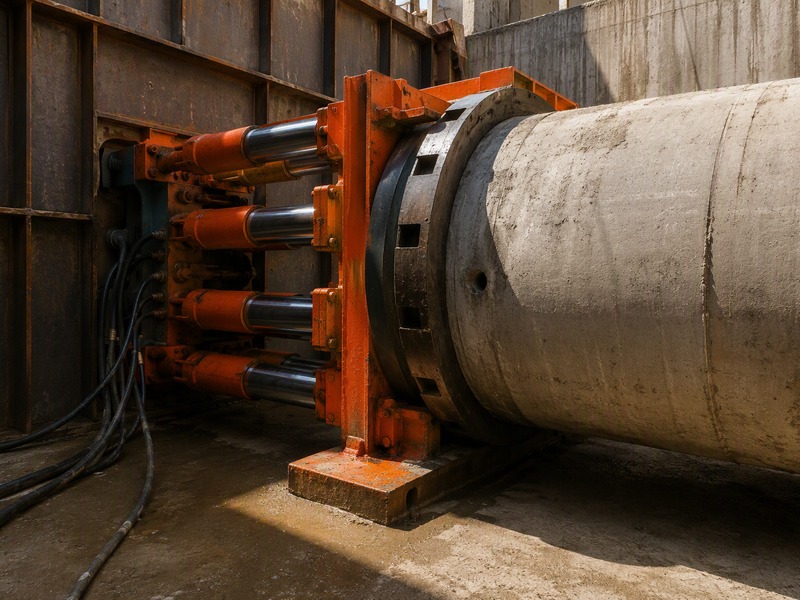
The jacking frame sits in the launch shaft, backed by a thrust wall that transfers the reaction into the ground or the shaft structure. As much as hundreds of tonnes of force may be required, and the entry shaft has to resist it without moving. The thrust ring spreads that load evenly around the pipe end so the first pipe is not crushed, and the pipe manufacturer’s permitted joint deflection governs how far the line can curve. In our bid reviews the thrust wall is one of the first items we test, because an under-designed wall shows up later as shaft movement and lost grade.
Overcut, bentonite lubrication and friction
The annulus and the friction it carries are two ends of one decision; the published figures are in Table 2. Our field teams record lubrication volumes and jacking force at each push, because a rising force curve warns that the annulus is not being maintained.
Interjack stations and long drives
When friction plus pipe weight exceeds what the initial frame can push, an intermediate jacking station between two pipes pushes a section of the string while the main frame pushes the rest. Pipe Jacking Association indicative jacking lengths for mechanised drives rise with diameter, from about 150 m at diameters under 0.9 m to about 1,000 m at 1.9–2.1 m; Table 2 sets out the figures used for Rule 4. On extended drives, interjack stations are typically deployed roughly every 100–150 m. Where a jacked main later needs attention, dịch vụ lắp đặt đường ống and repair crews work from the shafts.
Rule 4: Face Support – The Rule That Filters Out Plain Auger Boring
Face support is the rule that filters out plain auger boring: the face is held while the machine advances. Face support keeps the ground at the cutterhead from running in, and it is the rule that most often decides whether a proposed scope qualifies. Face support also links the machine to settlement: ground loss at the face and along the annulus is what shows up at the surface.
Pressurized slurry, EPB and auger: three face conditions
The Pipe Jacking Association groups microtunneling machines into two types, pressurized slurry and auger, both having face support capability. Slurry microtunneling balances the face with a pressurized bentonite or water slurry pumped to the cutterhead and returned to a separation plant. EPB machines are used for larger pipe jacks, are often applied in cohesive soils, and condition the spoil with bentonite, water or polymer in mixed faces.
An open-face auger machine removes spoil on a screw conveyor and relies on the ground standing on its own, so it does not develop a controlled support pressure. In the four-rule frame, a plain open-face auger without face support does not meet the definition, even when the machine is guided and the pipe is jacked. Where the ground is dry and stable it can still be an appropriate choice; it is simply a different method.
Ground loss, overcut and settlement
Face support does not remove settlement risk; it manages it. That is the trade inside Rule 4: a larger annulus makes the pipe easier to jack, and a smaller annulus makes the surface easier to protect. On drives we have supported under live roads, settlement trigger levels were set before launch and measured after each push.
How Do You Test a Proposed Scope Against the Four Rules?
Table 1 is the working form of the microtunneling definition.
| Rule | What it requires | What fails without it | How it is checked in a bid |
|---|---|---|---|
| Rule 1 – Remote control | No man entry; the machine is driven from a surface cabin with telemetry for guidance, steering, thrust and spoil | A manned heading (conventional tunneling) or a machine called remote with no telemetry loop to steer from | Control philosophy, cabin equipment list, telemetry schedule, entry-seal plan |
| Rule 2 – Guidance | Active line and grade control to a stated tolerance; laser target and theodolite total station, water leveling, gyro or inertial units on curves and deep drives | An unsteered or visually aimed drive (auger boring) that loses grade over distance | Stated tolerance, guidance system model, survey and check-frequency method statement |
| Rule 3 – Pipe jacking | Jacking frame and thrust wall; thrust ring; jacking pipe joints that carry thrust; overcut with bentonite lubrication; interjack stations where force requires | A liner installed by other means, or a segmental lining (conventional tunneling) | Thrust calculation, thrust wall design, pipe joint and packer details, lubrication plan |
| Rule 4 – Face support | Controlled support pressure at the cutterhead; pressurized slurry, EPB, or a supported auger face | An open face with no support pressure (open-face auger or jack-and-bore), leading to uncontrolled ground loss and settlement | Machine type and face-support mode, support-pressure control loop, settlement trigger levels |
Settlement and Overcut: Reading the Numbers Behind Rule 4
Rule 4 is where the numbers get tightest, because the same annulus controls both jacking friction and surface movement. Table 2 collects the published figures that decide Rule 4: the annular overcut, friction and tolerance. Friction and jacking-length values are Pipe Jacking Association figures; the diameter position is stated by ASCE/CI 36-15.
| Tham số | Published or typical value | What it controls | Design implication |
|---|---|---|---|
| Annular overcut | Typically 13–38 mm (1/2 to 1.5 in) | Jacking friction and ground loss | A larger gap eases pipe jacking; a smaller gap protects the surface |
| Overcut settlement risk | A 35 mm overcut is the annulus width at which surface subsidence becomes possible | Surface movement under roads and railways | Reduce the overcut at road and rail crossings so that surface movement stays below about 10 mm |
| Friction, unlubricated | 0.5 to 2.5 tonnes per square meter of external circumferential area | Required jacking force and drive length | Plan lubrication from the first push rather than reacting later |
| Friction, lubricated | As little as 0.1 tonnes per square meter | Required jacking force and drive length | Bentonite injection can extend a drive before an interjack station is needed |
| Tolerance | Typically ±50 mm of true line and level in stable homogeneous ground | Alignment and grade at the receiving structure; the published value assumes stable, self-supporting, homogeneous ground. | Tighter tolerances may require a larger pipe or a different guidance system |
The ASCE/CI 36-15 Position: A Method, Not a Diameter Limit
ASCE/CI 36-15, Standard Design and Construction Guidelines for Microtunneling, published in April 2015, states that microtunneling describes a method and does not impose size limitations on diameter. That single sentence is why a criteria-based microtunneling definition is more useful than a diameter rule: the standard treats the method, not the size, as the thing being specified.
Market convention still separates small remote-controlled drives from large manned tunnels, but it is convention rather than rule. A scope that is remotely controlled, guided, jacked and face-supported is applying the method at whatever diameter the design calls for. Where a project instead requires man entry, a segmental lining or a bolted ring, it has moved into conventional tunneling regardless of how small the drive is.
Eurocode 7, the jacking-pipe standards EN 1916, BS EN 295-7 and BS EN 12889, and ASTM F1962 regulate the ground, the pipe and the execution, and leave the size question to the design.
Frequently Asked Questions About the Microtunneling Definition
Is a microtunneling definition based on diameter or on method?
The definition is based on method, not diameter. ASCE/CI 36-15 states that microtunneling describes a method and does not impose size limitations on diameter. The figures you see quoted, such as a working range of about 0.35–4 m or a jacking pipe range of 150–2,400 mm, describe what the equipment commonly covers rather than a boundary in a standard.
Why can a person not drive a 900 mm microtunneling machine?
A 900 mm drive leaves no room for a person once the machine is inside it. The shield, cutterhead drive, spoil path and guidance target fill the section, and published descriptions note that at these diameters it is not possible to have an operator driving the machine, so the machine is remotely operated.
What tolerance does the microtunneling definition imply?
A stated tolerance, typically plus or minus 50 mm of true line and level. Pipe Jacking Association guidance gives that figure for stable, self-supporting, homogeneous ground and notes that tighter tolerances may not be attainable in unstable ground or where obstructions are found. JSW’s laser-guided work is quoted at about plus or minus 25 mm.
Does an open-face auger machine meet the microtunneling definition?
An open-face auger machine qualifies only when it develops a controlled support pressure. An auger machine relies on the ground standing on its own, so it meets the face support rule only where the face is stable without continuous support. For a 2.4 m drive that is still remotely controlled and face-supported, the four rules apply unchanged; the label changes, the eligibility test does not.
Why does pipe jacking matter in the microtunneling definition?
Because the jacked pipe is the permanent lining, not a temporary casing. The pipe must carry the jacking thrust, its joints must transmit that thrust without crushing, and the annulus must be lubricated to keep friction in range.
What does ASCE/CI 36-15 say about diameter limits?
ASCE/CI 36-15 frames microtunneling by method rather than by size, and sets no diameter limit. The standard was published in April 2015.
Key Takeaways
- A microtunneling definition is a method test, not a diameter test: remote control, guidance, pipe jacking and face support applied together.
- Remote control means no man entry. A 900 mm drive cannot hold an operator, so a microtunneling machine is driven from a surface cabin over telemetry.
- Guidance turns a drive into a controlled line and grade; published tolerance is typically ±50 mm in stable homogeneous ground, with a stated tolerance required for gravity sewers.
- Pipe jacking supplies the permanent lining and sets the drive’s force limits; lubrication can cut friction from 0.5–2.5 tonnes per square meter of external circumferential area to 0.1.
How JSW Supports Microtunneling Definition and Eligibility Reviews
JSW is a pipeline engineering and construction company that executes trenchless crossings with its own crews and equipment. Our scope covers microtunneling construction, pipeline installation services, trenchless technologies, pipeline inspection service and pipeline repair services.
For an eligibility review, the useful input is the design intent: diameter, drive length, depth, ground profile and the tolerance the design actually needs. We install pipelines from DN300 to DN1500 (12–60 inches) by microtunneling, with single drives up to 600 m, laser guidance accuracy of about ±25 mm using a VMT laser guidance system, installation depths of about 2–25 m, and interjack stations deployed roughly every 100–150 m for extended drives. Ground capability runs from soft clay and sand through cobbles and mixed ground to hard rock up to about 80 MPa UCS.
- Integrated delivery: shafts, jacking, guidance, pipe supply and reception are planned as one sequence by one team.
- Auditable process data: guidance checks, jacking force and lubrication records are kept per push and can be issued with the as-built.
- Risk-explicit pricing: ground risk, obstruction risk and settlement triggers are named in the proposal rather than absorbed silently.
- Certified systems: JSW holds ISO 9001:2015, ISO 14001:2015 and ISO 45001:2018 certification, and recommendations are reviewed by professional engineers before bid.
Not sure whether your proposed scope meets all four rules? Send your diameter, drive length, ground profile and required tolerance for a free technical review. Our engineers reply with a rule-by-rule eligibility read-out and an indicative budget range.





































 English
  Arabic
  Russian
  Spanish
  French
  Vietnamese
  Polish
  Thai
Thai  Indonesian
  Turkish
  Portuguese