
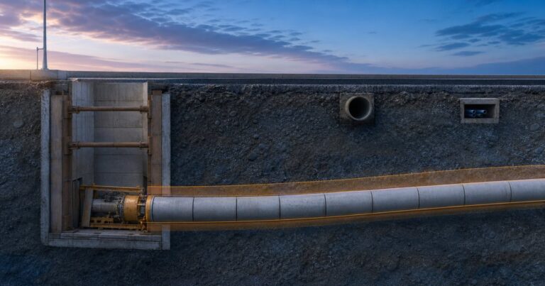
Microtunneling tolerances – the permitted departure of a remotely controlled, non man-entry jacked pipe from its design alignment – define how far the installed pipe may sit from its design line (horizontal position in plan) and its design grade (the designed fall, expressed as a percentage or an elevation), and they are the first thing a designer must fix before any thrust calculation or shaft layout. Published values range from about ±25 mm in line and level for well-controlled microtunneling to roughly ±50 mm for typical pipe jacking, widening to ±100 mm or more on a casing where back fall does not matter. Set the microtunneling tolerances from the pipe’s duty, not from the machine: a gravity sewer is usually written at ±50 mm horizontal, ±30 mm vertical and ±0.25% grade with no back fall, while a casing that only carries a product pipe is often written at ±500 mm, ±100 mm and ±1%. The band actually achieved adds the five error sources together, and it is often wider than the paper requirement.
What Do Line, Grade and Tolerance Mean in a Microtunneling Design?
Line is the horizontal position of the pipe centerline in plan. Grade is the designed fall of the pipe, expressed as a percentage or as a vertical elevation, and tolerance is the permitted departure from either. The three are named separately in every microtunneling specification: horizontal (line) tolerance, vertical (grade) tolerance and grade (slope) tolerance. A tolerance is always quoted against the reference alignment (the approved line and grade the drive is set out from).
For a gravity sewer, grade is functional, not cosmetic. The pipe has to fall continuously in one direction so that flow keeps moving and solids do not settle. If the installed pipe dips below the design invert in one reach and rises above it in the next, the line can develop a local low point and water ponds there. That is why a sewer specification usually names three separate tolerances rather than one general figure.
- Horizontal tolerance – lateral departure from the design line, in plan.
- Vertical tolerance – departure of the invert from the design elevation.
- Grade (slope) tolerance – permitted error in the fall over the drive, usually expressed as a percentage such as ±0.25%.
Taken together, these three numbers are the microtunneling tolerances that the design must fix before construction begins. They also decide how much a joint is allowed to articulate, because the alignment can only be corrected within the manufacturer’s permitted joint deflection.
For a casing, liner or sleeve that carries a product pipe later, the picture is different. A casing rarely carries gravity flow, so its pipe jacking tolerance can be generous and the tight requirement is transferred to the carrier pipe inside it. Understanding which of the three numbers actually governs the asset is the first design decision, and it determines how much guidance, survey and steering effort the drive needs.
Why Tolerances Matter More for Gravity Sewers Than for Casings
The consequence of being out of line or grade is what sets the tolerance, not the pipe diameter. On a gravity sewer a small vertical error can change the hydraulic capacity of the reach and can create ponding that leads to siltation and odor. On a pressure main or a casing the pipe either holds pressure or simply protects a carrier, so a deviation that would fail a sewer is often acceptable.
The Unitywater Pr9787 specification for microtunneling and pipejacking illustrates the split clearly. For gravity sewers it sets horizontal tolerance at ±50 mm, vertical tolerance at ±30 mm and tunnel grade at ±0.25%, with no back fall and no ponding allowed. For casing pipes used for other applications it relaxes the same three numbers to ±500 mm horizontally, ±100 mm vertically and ±1% grade. The geometry of the drive may be identical; only the duty of the pipe changes.
Two allocation rules decide how the numbers are applied. First, the tolerance band is a budget for the whole drive, so shaft setting-out error and machine guidance error share it: the check differential measured at the shafts is what gets amplified along the drive. Second, the grade tolerance and the vertical tolerance bind in different places – over a 100 m drive a ±0.25% grade tolerance is about ±250 mm of fall, an illustrative figure only, so the ±30 mm vertical band is normally the governing limit and the grade tolerance governs only where the design fall is shallow enough for a small vertical error to reverse it. The design should state which of the two governs for each reach.
If the question is whether a specific 400 m gravity sewer drive can be accepted at ±25 mm, the answer is fixed by the pipe’s duty and the five error sources, not by the clause itself. A gravity sewer and a casing can be built with the same machine in the same ground and still carry entirely different microtunneling tolerances, because the consequence of deviation is different. Set the tolerance from the pipe’s duty first: what the pipe has to do over its service life fixes the vertical and grade limits, and the machine and guidance capability then tells you whether those limits are reachable in the ground the drive will actually cross.

What Tolerance Values Do Published Specifications Actually Give?
The values below are not interchangeable targets: each row answers the same three questions – horizontal departure, vertical departure and permitted slope error – for a different pipe duty, ground condition or level of control, and the row that matches your pipe’s duty is the one to design to.
| Application or condition | Horizontal (line) | Vertical (grade) | Grade slope | Published source |
|---|---|---|---|---|
| Gravity sewer | ±50 mm | ±30 mm | ±0.25% | Unitywater Pr9787, Specification for Microtunneling and Pipejacking |
| Casing for other applications | ±500 mm | ±100 mm | ±1% | Unitywater Pr9787, Specification for Microtunneling and Pipejacking |
| Typical pipe jacking, stable ground | ±50 mm | ±50 mm | not stated in this source | Pipe Jacking Association (PJA) |
| Attainable microtunneling, stable ground | ±25 mm | ±25 mm | not stated in this source | Pipe Jacking Association (PJA) |
| Commonplace design specification | ±1 in. (25 mm) | ±1 in. (25 mm) | not stated in this source | Tunnel Business Magazine / North American Microtunneling Association, article on specifying microtunneling installation tolerances |
| Practical installation tolerance | ±6 in. (150 mm) | ±3–4 in. (75–100 mm) | not stated in this source | Tunnel Business Magazine / North American Microtunneling Association, article on specifying microtunneling installation tolerances |
The Pipe Jacking Association’s figures are conditional: the ±50 mm typical value and the ±25 mm attainable value apply in stable, self-supporting, homogeneous ground and are not readily attainable in unstable ground or where obstructions are present.
The Tolerance Stack-Up: Five Error Sources That Add Together
Every installed pipe lands somewhere inside a band created by several independent errors. The five sources below account for most of the deviation an owner will actually measure.
| Error source | What it contributes | Published anchor |
|---|---|---|
| Pipe fabrication | Built-in dimensional variation in each pipe and joint | ID variance at 48 in.: RCP 0.79 in. (about 20 mm) (ASCE 27-00), VCP 1.44 in. (about 37 mm) (ASTM C1208), centrifugally cast FRP 0.48 in. (about 12 mm) (ASTM D3262), polymer concrete 0.48 in. (about 12 mm) (ASTM D6783); the variance can double if successive pipes deviate the same way |
| Guidance reporting | Position error of the guidance system | Guidance can report the target at the rear of the machine to about ±1 in. (25 mm); accuracy decreases as the drive lengthens through beam diffusion and refraction (published specifying article in Tunnel Business Magazine / North American Microtunneling Association) |
| Overcut | The annulus the machine cuts beyond the pipe outside diameter, so the pipe can sit anywhere inside the hole | 1/2 to 3/4 in. (13–19 mm) on the radius in soil, and more than 1 in. (25 mm) in rock (published specifying article in Tunnel Business Magazine / North American Microtunneling Association) |
| Geology | Forces that push the machine off line or wedge the pipe | Mixed face, mixed reach, weak soils with insufficient bearing capacity, soil over bedrock, boulders, weathered rock and rock cuttings causing pipe wedging |
| Shaft setting-out | Alignment error measured at the shaft, amplified along the drive | A 1/8 in. check differential in a 25 ft shaft produces roughly a 5 in. lateral shift at 1,000 ft (published specifying article in Tunnel Business Magazine / North American Microtunneling Association) |
Which Error Source Usually Governs the Achieved Tolerance?
Pipe fabrication usually sets the floor and guidance reporting usually sets the drift, so the two together explain most of the spread an owner measures.
The fabrication row deserves emphasis because it is the one error source fixed before the machine moves, which is why it belongs in the specification as its own line item rather than being left to the pipe standard. If successive pipes deviate in the same direction the variance in the table can double, and the deviation is then locked into the installed line.
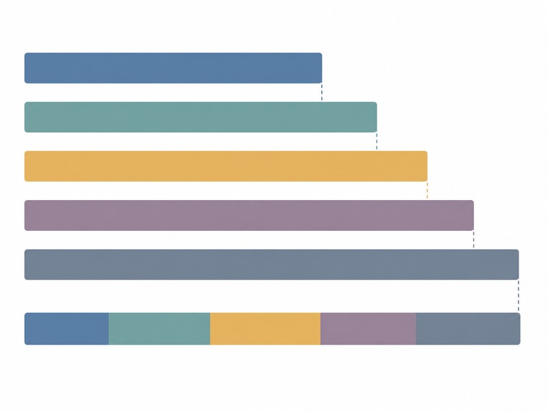
In our design reviews we treat the five error sources above as one budget.
Take the 48 in. ID case: published allowable ID variance is 0.79 in. (about 20 mm) for reinforced concrete pipe to ASCE 27-00, so against a ±25 mm paper requirement the fabrication item alone can consume most of the band. The remaining room then has to be bought back by stricter pipe fabrication tolerance, a more precise guidance check, or a change of pipe duty.
Why a Blanket ±1 in. Specification Often Fails
If a specification calls for ±1 in. (25 mm) vertical and horizontal tolerance, the practical question is whether that band is reachable in the ground on this drive. The practical band is wider than the paper requirement because five independent errors add together: pipe fabrication, guidance reporting, overcut, geology and shaft setting-out. When microtunneling tolerances are written closer than that sum, a ±25 mm pipe jacking tolerance clause is satisfied on paper and missed on site.
A practical pipe jacking tolerance that adds pipe fabrication, geology, overcut and guidance could be as high as ±3–4 in. (75–100 mm) on grade and ±6 in. (150 mm) on alignment. That is a published observation about what is realistically achievable, and it explains why so many tight specifications end in a concession negotiation rather than a clean acceptance.
A specifiable tolerance is written in three parts: one band per reach, the ground and depth assumptions the band depends on, and the fabrication tolerance as its own line item. That makes the figure checkable before bid. Where a tight tolerance is truly non-negotiable, it should be reached by design rather than by wishful specification.
Design Deliverables an Owner Should Demand Before Bid
Tolerance is not something a contractor can simply promise: a municipal sewer owner, an EPC bidder pricing the drive, and a third-party design consultant all need the same three numbers proven rather than promised. The design deliverables below are what makes those numbers defensible. The Unitywater Pr9787 specification lists these obligations clearly, and they map well onto any microtunneling project.
- Alignment plan and long-section profile, showing line, grade, shaft positions and the tolerance band to be met.
- Shaft design, including a thrust wall certified to carry the maximum anticipated jacking force.
- Maximum jacking force and pipe capacity calculations, demonstrating that pipes and joints will not be overstressed, including the selection and spacing of intermediate jacking stations.
- Settlement calculations from overcut and over-excavation at the cutting face, with mitigations such as annulus grouting, forming the basis of a ground settlement monitoring plan.
- A monitoring plan and dilapidation reports covering the work sites and the surrounding area likely to be affected.
The dilapidation coverage is often under-specified, so it is worth fixing the extent explicitly. The same specification requires coverage of at least 3 × the depth of any shaft measured radially from its perimeter and 2 × the depth to invert measured from the pipe centerline, plus any area inside the settlement trough or zone of influence.
On the drives we have supported, the projects that hold tolerance most reliably are the ones where guidance system, check frequency and correction limits were agreed in the design, before the machine was lowered into the shaft; those three are set out in our grade control and steering accuracy guide, and the overcut contribution to this stack-up is treated in our overcut, lubrication and settlement guide.
When Tight Tolerance Is Functional: Design Remedies That Buy Accuracy
Where grade genuinely governs the asset, there are proven design levers that widen the gap between the microtunneling tolerances written in the specification and what can be achieved. None of them is free, and each trades cost, time or hydraulic capacity against precision. They should be selected deliberately and recorded in the design.
- Two-pass system. Jack a casing or sleeve first at a relaxed tolerance, then install the carrier pipe inside it to meet the tight final line and grade. The jacking tolerance and the product-pipe tolerance are separated.
- Oversized pipe with a new invert. Install a larger pipe and cast a new invert at the design elevations, so minor vertical deviation is absorbed by the lining.
- Ground improvement. Treat the ground where grade is critical so the machine has uniform resistance and does not wander.
- Steeper design slopes. Where the hydraulic design allows, a steeper slope widens the permissible vertical tolerance for the same consequence.
- Stricter pipe fabrication tolerance. Specify dimensional control tighter than the standard where the stack-up leaves no room.
- Contractor prequalification. Select a contractor with a demonstrated guidance and steering capability for the diameter and ground in question.
These remedies also interact with the diameter and length of the drive. The joint deflection permitted by the pipe manufacturer must never be exceeded at any joint, regardless of how much the machine could steer, and line and grade should be adjusted gradually rather than in one correction. The achievable tolerance is the tighter of two limits: the band written in the specification and the manufacturer’s permitted joint deflection at each joint. Where the second is the binding one, the remedy is a changed pipe duty or a redesigned alignment – not a tighter steering target.
Frequently Asked Questions About Microtunneling Tolerances
What is a realistic microtunneling tolerance?
If the question is how much tolerance a sewer drive of a given length and depth can realistically hold, the published starting point is about plus or minus 50 mm in stable, self-supporting ground. A gravity sewer specification is usually tighter, around plus or minus 50 mm horizontally and plus or minus 30 mm vertically with a grade tolerance of about 0.25 percent, and no back fall is allowed.
Why is a plus or minus 1 inch specification hard to hit?
A plus or minus 25 mm specification is commonplace but often difficult or impossible to achieve, because pipe fabrication, geology, overcut and guidance errors add together. A practical installation tolerance can be as high as plus or minus 75 to 100 mm on grade and plus or minus 150 mm on alignment.
What does grade mean for a gravity sewer?
Grade is the designed fall of the pipe, and for a gravity sewer it must stay monotonic so the line never runs uphill and water never ponds. For a gravity sewer the vertical and grade tolerances therefore govern acceptance, and the horizontal tolerance governs only where the pipe enters an existing structure.
How does shaft length affect line and grade?
A small alignment error measured over the shaft length is amplified along the drive. Because the same amplification applies to the setting-out itself, the shaft reference marks are checked against an independent control point before the machine is launched, and the check value is recorded with the as-built records.
What is a two-pass system?
In a two-pass system a casing or sleeve is jacked first to a relaxed tolerance, and a carrier pipe is then installed inside it to meet the tight final line and grade. It separates the jacking tolerance from the product-pipe tolerance and is common where grade is critical.
Can tolerance be improved after the pipe is installed?
Tolerance is recovered by design, not by moving the installed pipe. The practical remedies are designed in advance: an oversized pipe with a new invert cast at design elevation, ground improvement, steeper design slopes to widen the permissible vertical tolerance, stricter pipe fabrication tolerances and contractor prequalification.
Key Takeaways
- Microtunneling tolerances have three parts: horizontal line, vertical grade, and permitted slope error – and which one governs depends on the pipe’s duty.
- For a gravity sewer the vertical and grade tolerances govern acceptance, because grade must stay monotonic; for a casing the horizontal tolerance usually governs the carrier installation.
- In stable, self-supporting ground, published figures are about ±50 mm typical and ±25 mm attainable; gravity sewers are tighter, and the band actually achieved is the sum of five error sources – a practical band of ±3–4 in. on grade and ±6 in. on alignment has been documented.
- Design remedies that buy accuracy include a two-pass system, oversized pipe with a new invert, ground improvement, steeper slopes, stricter fabrication tolerances and prequalification.
- Shaft setting-out error is amplified along the drive, so the reference alignment at the shafts deserves the same care as the machine guidance.
- A tolerance is written per reach, with its ground and depth assumptions and with the fabrication tolerance as its own line item – that is what makes it checkable before bid.
- Every value here is an input to project-specific design, not a substitute for it; a competent engineer must confirm line, grade and tolerance for the actual drive.
How JSW Supports Microtunneling Design and Tolerance Control
JSW is a pipeline engineering and construction company that executes trenchless drives with its own crews and equipment. Our scope covers microtunneling construction, where the line, grade and tolerance of the drive are set, together with dịch vụ lắp đặt đường ống for the carrier pipe. Where a crossing needs a different method, we also deliver other trenchless technologies. Where an installed line has to be verified before acceptance, JSW provides a pipeline inspection service; where a deviation has to be corrected in service, we provide pipeline repair services.
Because we both design and construct, tolerance requirements are set against the equipment and ground we will actually meet on site, not against a generic catalogue figure. Our design deliverables are auditable: alignment and profile, thrust and pipe capacity calculations, settlement predictions and monitoring plans are documented and reviewed before bid. Pricing is risk-explicit, so an owner can see what drives cost and what drives precision.
- Integrated delivery: design, shaft construction, jacking and commissioning under one accountable team.
- Auditable records: guidance data, jacking records and as-built alignment handed over in reviewable form.
- Risk-explicit pricing: tolerance and ground risk identified and priced openly rather than carried as contingency.
- Safety and compliance: drives planned around OSHA and HSE expectations and the named pipe and jacking standards.
Unsure whether your line and grade tolerance is achievable in the ground you have? Send your alignment profile, pipe diameter and ground investigation for a free technical review. Our engineers reply with a scoped recommendation, the reach-by-reach band we would expect to govern, the assumptions it depends on, and an indicative budget range.





































 English
  Arabic
  Russian
  Spanish
  French
  Vietnamese
  Polish
  Thai
Thai  Indonesian
  Turkish
  Portuguese