
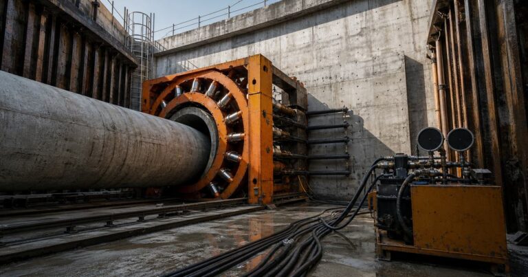
Microtunneling jacking force is the total thrust the jacking frame must deliver to advance the machine and push the pipe string from the launch shaft, and it is the sum of face resistance at the machine, friction along the pipe string, and any force added by curvature. Published friction values fall between 0.5 and 2.5 tonnes per square meter of external circumferential area, but lubricant injection can reduce them to as little as 0.1 tonnes per square meter. Every term in the budget is carried back to the launch shaft, so the thrust wall (the structure that provides the jacking reaction) must be designed for the total jacking force, and the force-versus-distance curve must stay below the pipe’s allowable jacking load at every stage. This page sets out the force budget, the named calculation approaches, machine and pipe capacity, intermediate jacking stations, and the instrumentation that keeps a drive inside its limits.
What Makes Up the Microtunneling Jacking Force Budget?
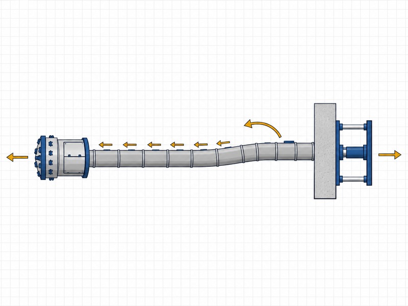
The force budget has four terms, and a design that leaves any of them out will underestimate the thrust it must provide. Face resistance acts at the machine, pipe friction acts along the pipe string, curvature adds a component whenever the alignment bends, and the whole sum is reacted by the reaction wall at the launch shaft.
- Face and penetration resistance – the resistance of the ground being cut at the machine.
- Pipe friction resistance – friction over the external circumferential area of the pipe string.
- Curvature contribution – added load where the machine and pipe sections are deflected along a curve.
- Reaction at the thrust wall – the structure that must carry the total without yielding.
Two named methods are widely used for the calculation. Apply them with a competent engineer: the German ATV A-161 jacking force calculation and the Concrete Pipe Association of Australasia (CPAA) Jacking Design Guidelines are the recognised approaches, and the CPAA guidance also covers allowable loads and deflections.
Face and Penetration Resistance at the Machine
Face resistance is often a large share of the microtunneling jacking force budget, and it is the term least tied to drive length. It depends on the ground at the face, the cutterhead design and the face support pressure being maintained, so it is confirmed from the ground investigation rather than assumed. In stiff cohesive ground the machine must shear and cut; in granular ground it must hold a supported face while the spoil is removed.
Face support is what keeps the resistance predictable. A slurry microtunneling machine provides earth pressure to balance lateral earth loads and slurry pressure to balance groundwater pressure, and the machine type is chosen to suit the ground. If the support pressure falls, the face moves, the machine loses line, and the resistance changes in ways the thrust calculation did not anticipate. The face term is therefore as much a control problem as a calculation term.
The machine is also the point where the available thrust is generated. A large slurry microtunneling machine’s jacking frame is described by its manufacturer as advancing the machine with up to 1,200 tonnes (metric tonne) of thrust. That capacity is a machine statement about one product, not a general limit, but it illustrates the order of magnitude that large drives can require.
Pipe Friction Resistance Over the External Circumferential Area
Pipe friction resistance is the term that grows with drive length, and it is the reason long drives eventually need help. It is calculated over the external circumferential area of the pipe string, using a friction value that depends on the ground and on whether the annulus is lubricated. Published values give a clear envelope for each component of the force budget. A municipal sewer owner checking a specification, an EPC bidder pricing a long drive, or a contractor’s design team sizing the jacking frame all work from the same components.
| Force component | What it represents | Published anchor |
|---|---|---|
| Face and penetration resistance | Resistance of the ground being cut at the cutterhead | Ground-dependent; a large slurry machine’s jacking frame is rated to about 1,200 tonnes of thrust (manufacturer statement) |
| Pipe friction resistance | Friction over the external circumferential area of the pipe string | 0.5–2.5 tonnes per square meter (t/m²) of external circumferential area, reducible to about 0.1 t/m² with lubricant injection (PJA) |
| Curvature contribution | Load added where the machine and pipe sections are deflected along a curve | Jacking loads increase significantly on a curve (published guidance on curved microtunneling drives) |
| Reaction at the thrust wall | The structure that carries the total jacking load | The thrust wall must be designed for the anticipated jacking load (PJA) |
The friction envelope of 0.5 to 2.5 tonnes per square meter comes from the Pipe Jacking Association, and it is the single most useful published reference for a first estimate. It is a range, not a value, and the design must pick a position within it based on the ground and on how reliably lubrication can be maintained. In rock or in a rough, unlubricated bore the term sits at the top of the range; in smooth, well-lubricated ground it falls toward the bottom. In our design reviews the friction value is chosen from the published range and then checked against the force measured over the first few pipes, so the budget is calibrated to the ground the drive actually meets.
Friction also rises with time: a drive that stops keeps transferring load into the ground, so the friction term can climb once the machine is stationary. That is why the force-versus-distance curve is watched continuously rather than sampled at the end of the drive.
How lubrication sits inside the wider trade-off between overcut, lubrication and settlement is set out in our overcut, lubrication and settlement guide, and the face support that keeps the resistance predictable is treated in our slurry microtunneling face support guide.
Lubrication: How Injection Cuts Friction Toward 0.1 t/m²
Lubrication is the main lever for reducing pipe friction resistance. Bentonite or polymer is injected into the annular space between the pipe and the bore, at a nominal pressure above groundwater pressure, to separate the pipe from the ground and turn dry friction into a lower-resistance interface. The published effect is large, and it is the reason lubrication is planned as a control system rather than as an occasional top-up.
For the injection to work, the fluid has to reach the surface that is generating the friction, and it has to stay there. Specification practice reflects this:
- Applies mainly to larger pipes. Outer annulus lubrication is used only in jacking pipes of DN1200 (nominal) or greater.
- Frequent, evenly distributed ports. Lubrication ports at minimum 15 m spacing, spread around the circumference at 120 degrees, with sealed one-way valves.
- Controlled delivery. Automatic set-volume or set-pressure injection is preferred to manual pumping.
- Biodegradable fluids. Drilling fluids must be biodegradable, so any loss to ground is not a long-term contaminant.
Plan the force budget for fluid loss: in permeable or fissured ground the bentonite can drain into the formation instead of forming a lubricating film, so the friction term climbs back toward the dry envelope. Where that risk exists, build the budget on a conservative friction value with margin rather than on the 0.1 tonnes per square meter figure.
The Rising Force-Versus-Distance Curve and Jacking Pipe Capacity
Because pipe friction resistance grows with the length of pipe in the ground, the force rises as the drive advances. If the question is whether a specific drive, such as a 600 m drive, can be completed without overstressing the pipe, the answer comes from plotting the predicted force against distance and comparing that curve with the allowable load of the pipe and joints at every stage, rather than from the final total alone. If the question is how much friction to assume with lubrication, the published envelope narrows from 0.5–2.5 tonnes per square meter to about 0.1 tonnes per square meter where injection is maintained above groundwater pressure. As long as the predicted curve stays below the pipe capacity line at every stage, the drive can be completed without overstressing the string; where the curve approaches that line, the response is to redistribute the load with an intermediate jacking station rather than to push harder.
Jacking pipe capacity is the allowable axial load the pipe and its joint can carry, and it comes from the manufacturer rather than from a general pipe standard, because a jacking pipe transfers load through the joint. The axial capacity is determined from the minimum wall thickness, concrete strength, packer properties and the joint deflections expected during installation. One manufacturer’s published fixed-collar envelope gives a useful sense of scale.
| Pipe size (DN) | Maximum jacking load per pipe (one manufacturer’s fixed-collar envelope) |
|---|---|
| DN300 | about 100 tonnes |
| DN600 | 240 tonnes |
| DN1000 | 515 tonnes |
| DN1200 | 650 tonnes |
| DN1500 | 840 tonnes |
| DN1600 | about 1,020 tonnes |
Jacking pipe capacity also constrains how the force may be shared. If the total required force approaches the pipe capacity, the drive needs the load redistributed rather than simply pushing harder.
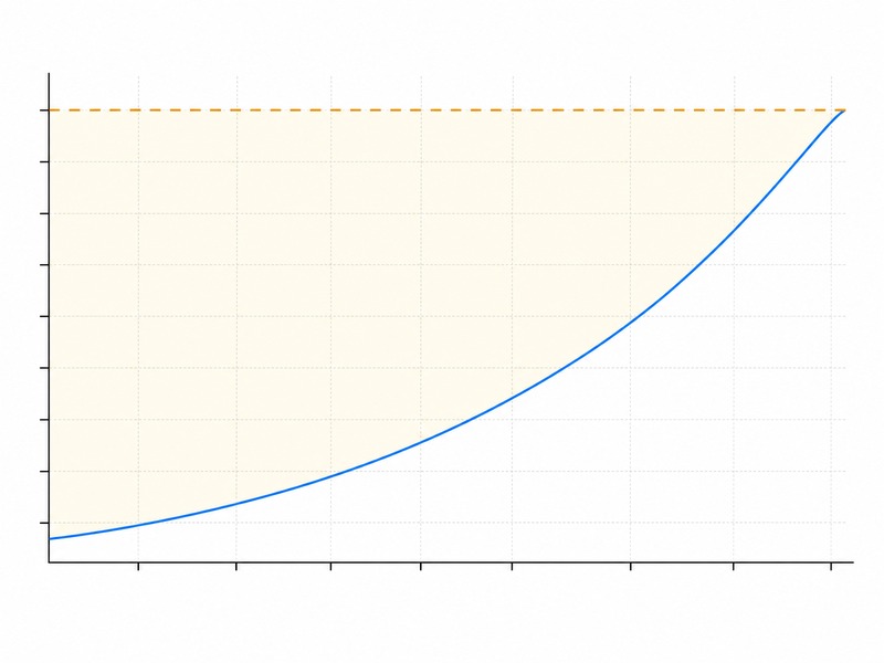
On long drives the jacking pipe capacity and the machine thrust rating should be checked together. Where a machine has thrust available that the pipe cannot accept, the design changes the force path, for example by redistributing the load, so the pipe stays within its allowable load.
How Are the Thrust Wall, Thrust Ring and Intermediate Jacking Stations Arranged?
Everything the machine pushes against has to be reacted somewhere. The reaction wall provides the jacking reaction and must be designed for the anticipated jacking load; if it is undersized, the reaction is taken by ground that may not be able to carry it, and the shaft or the surrounding ground can move. Where the ground is weak or the shaft is shallow, the reaction wall is often built as piles, ground anchors or a structural frame rather than a simple bearing surface.
Between the thrust wall and the pipe, a thrust ring spreads the load around the pipe circumference, and the jacks are hydraulically interconnected so that the thrust is equal around the ring. The number of jacks depends on the pipe size, the pipe strength, the drive length and the expected friction, so the jacking frame is sized as part of the design rather than chosen from a catalogue on the day.
An intermediate jacking station redistributes the total jacking force along the pipeline. Instead of the launch jacks pushing the entire string, the string is pushed in shorter sections, which keeps any single pipe and joint below its capacity. The station has a second, sometimes more valuable, benefit: it reduces the load transmitted back to the shaft structure, which helps where the ground around the shaft is poor and the reaction wall is difficult to anchor. A published utility specification (Unitywater Pr9787) allows one intermediate jacking station every 100 m of drive unless a different spacing is justified and approved.
- Fitted from inside. Because the station is installed from within the tunnel, it is used only at ID 1200 mm or greater (internal diameter).
- Sleeves overlap the pipes. The steel sleeves must overlap each pipe by at least 150 mm.
- Engineer certification. The arrangement must be certified by a registered professional engineer.
- Spacing follows the curve. One station every 100 m is specification practice, and the actual spacing is set by the force-versus-distance curve, so a drive with a sharp force rise may need closer spacing while a short, low-friction drive may need none.
Instrumentation, Records and What Pushes Forces Above Prediction
A force budget is only useful if the actual force is measured. Launch-pit jacks must be fitted with calibrated pressure gauges so the jacking force can be read at any time, and the instrumentation must also measure thrust pressure, stroke position and stroke speed. Calibration is what turns the gauge reading from an indicator into a control value.
Jacking force and lateral displacement off line and level should be recorded at intervals not exceeding 200 mm or every 90 seconds, whichever is reached first. Our field teams record the same parameters on every drive, and the trend line is usually more informative than any single number: a force that is climbing faster than predicted tells the operator something about the ground before the pipe does.
Several conditions push forces above prediction:
- Mixed face and boulders – the cutterhead meets harder material and resistance rises at the face.
- Curves – the machine and the straight pipe sections behind it are deflected by reaction from the tunnel wall, adding load.
- Slurry loss and a damaged filter cake – support pressure cannot be maintained and the annulus lubricant is lost into the ground.
- Stoppages and time effects – a stationary pipe string transfers more load into the ground, so friction creeps up.
A rising force is answered in a fixed order: advance carefully, check and restore face support and lubrication, and confirm the excavated volume against the theoretical volume. If the force keeps climbing toward the pipe or wall limit, stop and reassess rather than push on.
Frequently Asked Questions About Jacking Forces in Microtunneling
What is microtunneling jacking force?
Microtunneling jacking force is the total thrust needed to advance the machine and push the pipe string from the launch shaft. It is the sum of face resistance at the machine, friction along the pipe string and any additional load created by curvature, all of which must be carried by the thrust wall.
How much friction acts on a jacking pipe?
Published friction values from the Pipe Jacking Association fall between 0.5 and 2.5 tonnes per square meter of external circumferential area. Lubricant injection at a nominal pressure above groundwater pressure can reduce them to as little as 0.1 tonnes per square meter.
What is an intermediate jacking station?
An intermediate jacking station is a set of jacks inserted between pipes that redistributes the total jacking force along the pipeline. It also reduces the load transmitted to the shaft structure, which helps where shaft ground is poor, and specification practice allows one every 100 m of drive.
Why is a thrust wall important?
A thrust wall provides the jacking reaction and must be designed for the anticipated jacking load. If the thrust wall is undersized, the reaction is taken by ground that may not be able to carry it, and the drive or the shaft can move.
How much jacking load can a jacking pipe carry?
Jacking pipe capacity is the allowable axial load confirmed by the manufacturer for the specific pipe and joint, because a jacking pipe carries its load through the joint. One manufacturer’s fixed-collar envelope rises from about 100 tonnes at DN300 to about 1,020 tonnes at DN1600, but the figure depends on wall thickness, concrete strength, packer properties and expected joint deflection.
What pushes jacking forces above prediction?
Mixed face ground, boulders, curves, slurry loss, stoppages and a damaged filter cake can all push forces above prediction, and the response is a controlled one. Advance carefully, check and restore face support and lubrication, verify that the excavated volume matches the theoretical volume, and if the force keeps climbing toward the pipe or thrust wall limit, stop and reassess rather than push on.
Key Takeaways
- The microtunneling jacking force is the sum of face and penetration resistance, pipe friction resistance, a curvature contribution and the reaction carried by the thrust wall.
- The design check is the whole force-versus-distance curve against the pipe’s allowable jacking load, with the machine thrust rating and the pipe’s allowable load checked together so the pipe stays within its allowable load even where the machine could push harder.
- Published friction is 0.5–2.5 tonnes per square meter of external circumferential area, reducible to about 0.1 tonnes per square meter with lubricant injection at a pressure above groundwater pressure.
- Jacking pipe capacity is the allowable axial load confirmed by the manufacturer for the specific pipe and joint; one fixed-collar envelope rises from about 100 tonnes at DN300 to about 1,020 tonnes at DN1600.
- An intermediate jacking station redistributes the load along the pipeline and reduces the load on a weak shaft; specification practice allows one every 100 m, used only at ID 1200 mm or greater.
- Calibrated pressure gauges and records of jacking force and lateral displacement at intervals not exceeding 200 mm or every 90 seconds are the basis of control.
- Mixed face, boulders, curves, slurry loss and stoppages push forces above prediction; every value here is an input to project-specific design and must be confirmed by a competent engineer for the actual drive.
How JSW Supports Microtunneling Jacking Force and Drive Control
JSW is a pipeline engineering and construction company that executes trenchless drives with its own crews and equipment. Our scope covers microtunneling construction, where the jacking force budget governs the drive, and other trenchless technologies. For the carrier pipe we provide dịch vụ lắp đặt đường ống, and where a pipeline is damaged or fragile we deliver pipeline repair services and emergency response and contingency maintenance for water, oil and gas and infrastructure owners.
We prepare microtunneling jacking force and jacking pipe capacity calculations as part of the design package, not as an afterthought, and we size thrust walls, jacking frames and intermediate jacking station spacing against the ground we expect to meet. Because we build what we design, the force budget is checked against our own equipment and against the calibrated records from the drive. Pricing is risk-explicit, so an owner can see what drives cost and what carries contingency.
- Integrated delivery: design, shaft construction, jacking and reception under one accountable team.
- Auditable force records: calibrated jacking data, force-versus-distance plots and as-built records handed over for review.
- Risk-explicit pricing: ground, curvature and stoppage risk identified and priced openly.
- Safety and compliance: drives planned around OSHA and HSE expectations and the named pipe and jacking standards.
Need a jacking force and pipe capacity check for a long or hard drive? Send your alignment, drive length, pipe diameter and ground investigation for a free technical review. Our engineers respond with a scoped recommendation, the friction value and intermediate jacking station spacing we would expect to govern, and an indicative budget range.





































 English
  Arabic
  Russian
  Spanish
  French
  Vietnamese
  Polish
  Thai
Thai  Indonesian
  Turkish
  Portuguese