
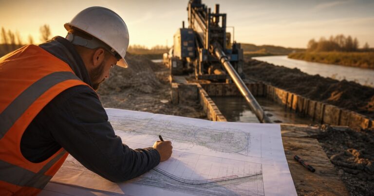
An HDD bore plan (a horizontal directional drilling bore plan) is built in one order: fix the survey datum, map obstacle offsets, set the cover requirements, fit the geometry, run the stress checks, then issue the drawing for construction. The plan is the drawing set that fixes where a bore travels, how deep it runs, how tightly it curves and how the product pipe is pulled back, turning an approved crossing into station-by-station instructions. This guide covers what the document contains, who owns each element, the order in which it is built and the checks that must pass before it is issued. Every dimension, ratio and check quoted below holds only until the actual crossing data is run; treat it as a planning aid, and confirm each value by calculation before the drawing is issued.
What Is an HDD Bore Plan, and What Must It Decide?
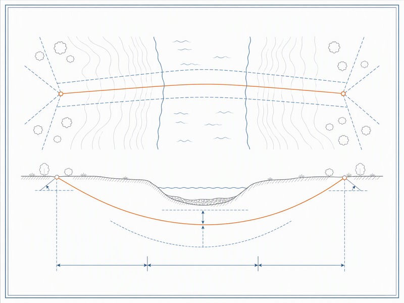
A bore plan has to decide six things, and a document that leaves any of them open is a section drawing rather than an instruction.
- Where the bore enters and exits, in survey coordinates and at an angle the rig can actually achieve.
- How deep the centreline runs at every station, below ground and below the crossing feature.
- How tightly it curves, against the allowable bend radius of both the drill pipe and the product pipe.
- How the hole is opened and cleaned, including the reaming sequence and the fluid plan.
- How the pipe is installed, with a pullback plan (also called the pullback sequence), buoyancy control and a stated tie-in tolerance.
- What happens when reality differs, through contingency triggers and a post-construction comparison.
The six decisions belong in one controlled drawing set because they interact.
What Goes Into the Bore Plan, and Who Signs Each Part?
The table below answers who owns each part of a bore plan and what evidence proves it correct. The plan is a multi-discipline document issued only once every row below has been signed, and the owner of a requirement does not sign off the check that proves it.
| Bore plan content | Who owns it | The check that proves it |
|---|---|---|
| Plan and profile sheet with stationing | Design lead | Chainage, bearings and surface features closed against the survey |
| Entry and exit coordinates and angles | Design lead | Coordinates tied to the survey datum and angles inside the achievable rig range |
| Centreline depth below ground and below the crossed feature | Design lead with survey support | Cover verified at every station, including under the feature |
| Bend radius and curvature | Design lead | Curvature compared with the allowable radius of drill pipe and product pipe |
| Rig position, anchors and setback | Drilling superintendent | Site layout confirms rig footprint, anchor plan and pipe string length |
| Drilling fluid plan | Fluids engineer | Volume, pressure and expected returns checked against the geotechnical profile |
| Reaming sequence | Drilling superintendent | Reamer sizes and number of passes checked against the product pipe outside diameter |
| Pullback plan | Drilling superintendent with design lead | Pull load calculation and rig capacity margin reviewed before make-up |
| Tie-in tolerance and contingency | Project engineer | Tolerance stated numerically and triggers agreed before mobilisation |
Which Two Elements Are Most Often Left Blank?
In our design reviews, the two rows most often left blank are the drilling fluid plan and the contingency, and both are usually completed by someone other than the person who drew the alignment. That separation is deliberate: the owner of a check should not be the author of the item being checked. The load components behind the pullback plan are set out in our HDD pullback load and stress analysis guide, and the ground data behind the fluid plan in our geotechnical investigation guide. The bore plan is also one of the deliverables named at the feasibility stage in our HDD feasibility and design guide, and the standards behind it are mapped in our guide to HDD design standards.
Two ownership rules keep that document honest. The person who sets a requirement does not sign off the check that proves it, and any element that depends on ground conditions is reviewed against the geotechnical profile rather than against a previous crossing in the same corridor.
How Is an HDD Bore Plan Built, Step by Step?
The order below is fixed because each step narrows the range available to the next: datum, obstacle offsets, cover, geometry fit, stress checks, then issue.
| Step | What it fixes | Output produced |
|---|---|---|
| 1. Fix the survey datum | Horizontal and vertical reference for every coordinate | Surveyed plan and profile with a stated datum and chainage |
| 2. Map obstacle offsets | Position and depth of every feature the bore must clear | Offset schedule backed by records and potholes |
| 3. Set cover requirements | Minimum depth below ground and below the crossed feature | Cover envelope along the full alignment |
| 4. Fit the geometry | Entry and exit angles, curvature and total length | Centreline that satisfies cover and bend radius together |
| 5. Run the stress checks | Allowable tension, bending and buckling of the product pipe | Installation stress calculation and rig capacity margin |
| 6. Issue the plan | Approval, revision control and construction hold points | Issued-for-construction bore plan |
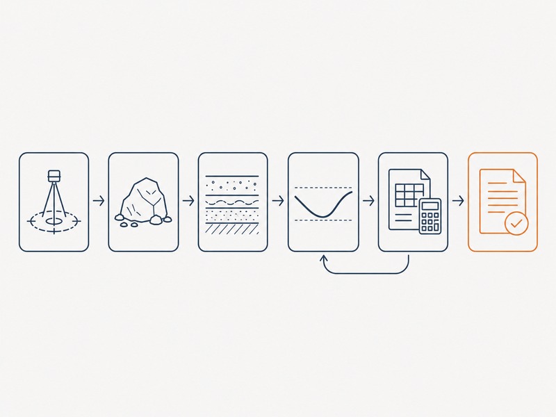
A centreline that clears every obstacle can still fail the curvature check, and a curve that satisfies the drill pipe can still over-stress the product pipe, which is why the geometry stage cannot be completed before cover and the geotechnical profile are fixed.
Stress checks at step five follow the framework in ASTM F1962, the standard guide for maxi-HDD placement of polyethylene pipe and conduit under obstacles including river crossings, with ASCE Manual of Practice 108, Pipeline Design for Installation by Horizontal Directional Drilling, on the pipeline-design side. The editions in force at the time of writing are F1962-22 and the more recent F1962-25, and a revision work item (WK93768) proposes an 8% deflection limit across DR ratings; the edition should be confirmed before issue.
How Do You Fit the Bore Geometry and Check Curvature and Cover?
Four values fix the bore geometry: entry and exit angles (commonly quoted at 8° to 18°), bend radius, depth of cover, and the reamed hole diameter. The geometry is settled by working through these four linked values rather than by preference. They have to be satisfied at the same time, and no single one can be fixed in isolation.
- Entry and exit angles: published practice puts these in the 8° to 18° band for typical crossings, governed by rig capability and the rate at which depth must be gained to hold cover.
- Bend radius: as planning aids, drill pipe is often estimated at roughly 100 to 200 ft of radius per inch of pipe diameter, and HDPE product pipe at about 25 to 35 × its outside diameter. A published rule of thumb for setback on a directionally straight profile is 5:1, derived from the effective bend radius.
- Cover: buried crossing cover is commonly specified in the 0.9 to 1.5 m range, with reviewed HDD projects sitting around a cover-to-diameter ratio near 1.5. Under a watercourse the depth is set by scour and bed stability rather than by a fixed figure.
- Reaming and guidance: the reamed hole is typically 1.2 to 1.5 × the product pipe outside diameter, following NASTT good practice, and walkover locating is practical to roughly 9 to 12 m in favourable conditions.
Fitting the bore geometry means finding one centreline that respects all four values at once. In our experience, the binding constraint is usually cover under the crossed feature rather than the curve radius, because cover cannot be increased locally without lengthening the bore.
Every figure above is a planning input; curvature, cover and stress are calculated for the actual crossing and confirmed by a competent engineer before the plan is issued.
What QA Checks Should Be Completed Before the Plan Is Issued?
Before issue, a bore plan should pass two groups of checks: hard gates that block the issue, and review items confirmed with the construction team.
Hard gates – the plan cannot be issued until these pass:
- Coordinate closure: chainage and coordinates close against the survey, with the datum stated on the sheet.
- Cover audit: depth is confirmed at every station, including the deepest point under the crossed feature.
- Curvature audit: no arc is tighter than the allowable radius of the drill pipe or the product pipe.
- Load versus capacity: the calculated pull load carries a stated margin against rig capacity, quoted as a percentage of the rated machine capacity used in the calculation.
Review items – confirmed with the construction team before mobilisation:
- Geotechnical alignment: the drilling fluid plan and reaming sequence match the strata the bore will actually pass through.
- Tolerance and contingency: tie-in tolerance is numeric and contingency triggers are agreed with the construction team.
- Approval trail: each owner has signed the element they own.
The plan is issued only when the drilling fluid plan and the reaming sequence have been checked against the geotechnical profile; a complete geometry on its own does not satisfy the issue gate. We have seen drawings that pass every paper check and still fail on site because the fluid plan was never matched to the ground.
How Is the Plan Reconciled With As-Built Deviation?
No long bore follows the centreline drawn on the plan exactly. Steering corrections, rod flex and changing ground conditions all move the pilot hole, so the plan and the as-built will differ.
The post-construction survey establishes where the bore actually ran and where the pipe finished. The post-construction survey is compared station by station with the plan, and that comparison is the evidence that the tie-in tolerance was met and that cover is intact under the crossed feature.
A bore plan is re-issued rather than annotated whenever the geotechnical profile, the pipe data or the working-area limits change, so the version on site matches the inputs it was built from.
How Is Tie-In Tolerance Set?
Tie-in tolerance is set from the capability of the downstream tie-in rather than from the bore: the survey accuracy of the guidance system, the expected deviation over that length and depth, and the adjustment range the tie-in allows are combined into one numeric tolerance before construction, and the construction survey is then compared against it station by station.
Our field teams record out-of-envelope stations as they happen, because a deviation found later is far harder to correct.
Questions fréquemment posées
What is an HDD bore plan?
An HDD bore plan is the controlled drawing set that defines the path, depth, curvature and installation sequence for a drilled crossing. It combines a plan view, a profile with stationing, entry and exit coordinates, cover and curvature checks, rig position and the construction sequence in one issued document.
What should an HDD bore plan contain?
It should contain the plan and profile with stationing, entry and exit coordinates, a centreline with depth below ground and below the crossed feature, bend radius and cover checks, rig position and anchors, the drilling fluid plan, the reaming sequence, the pullback plan, contingency and a numeric tie-in tolerance. Each element should name an owner and a verification check.
Who prepares a bore plan?
A bore plan is normally prepared by the crossing designer and reviewed by the drilling superintendent, fluids engineer and project engineer. On a design-and-build crossing one team may hold all four roles, which makes independent review more important, not less.
How accurate is an HDD bore plan compared with the as-built?
The plan defines an envelope and the as-built survey records where the bore actually ran within or outside it. Short bores with reliable guidance can track the plan closely, while long or deep bores accumulate deviation, which is why tie-in tolerance is set before construction rather than after.
What is the most common mistake in an HDD bore plan?
The most common mistake is building the geometry before the cover requirements and the geotechnical profile are fixed. The plan then looks correct in plan view but fails the curvature check, or the fluid plan cannot be matched to the ground the bore meets.
How deep should the centreline run under a river or a road?
Depth is set by the crossing authority and by scour or bed stability for watercourses, and by the asset owner for roads and rail. Buried crossing cover is commonly specified in the 0.9 to 1.5 m range, but under a river the number has to come from a scour assessment rather than from a table.
Points clés à retenir
- An HDD bore plan is a controlled instruction set, not a concept alignment: it fixes coordinates, depth, curvature, cover and sequence together.
- Every element needs a named owner and a check that proves it, which is why the fluids plan and the contingency are reviewed by someone other than the designer.
- Build the plan in order: datum, obstacle offsets, cover, geometry fit, stress checks, then issue.
- Rules of thumb for angle, bend radius and cover are planning aids only and must be confirmed by calculation for the crossing.
- Reconcile the plan with as-built deviation through a numeric tie-in tolerance, surveyed positions and a recorded comparison.
- Iterate freely before issue; the geometry stage is the cheapest place to absorb a changed constraint.
How JSW Supports HDD Bore Plan Development
JSW is a pipeline engineering and construction company that designs and delivers trenchless crossings using in-house engineers, crews and equipment. Our range includes HDD crossing services et technologies sans tranchée. It also covers automatic pipeline welding, pipeline cold bending et services d'installation de pipelines, so the plan we issue is one we can build.
Because the same team prepares the bore plan and then drills it, the geometry is fitted to the rigs, anchors and pipe string we will actually mobilise. Calculation sheets, the fluid plan and installation records are kept for review, and risk items are priced with their triggers stated rather than buried in a lump sum. Where a plan cannot be made to work, we say so before mobilisation.
- Prestation intégrée : one contract holds survey interpretation, bore geometry, stress checks, string fabrication and pullback, so design and construction interfaces sit with a single team.
- Auditable engineering: calculation sheets, the fluid plan and installation records are archived for construction review and later integrity management.
- Tarification tenant compte explicitement du risque : contingency items and their trigger conditions are priced openly instead of being buried in a lump sum.
- Crossing experience: watercourse, highway and rail crossings plus congested urban corridors, with permitting and reinstatement inside our scope.
Need a bore plan you can build from? Send the route survey, the geotechnical profile, the pipe data sheet, the utility records and the working-area limits for a free technical review. Our engineers reply with a scoped recommendation, the risks we see and an indicative budget, and name which hard gates above are still open on your crossing.





































 English
  Arabic
  Russian
  Spanish
  French
  Vietnamese
  Polish
  Thai
Thai  Indonesian
  Turkish
  Portuguese