
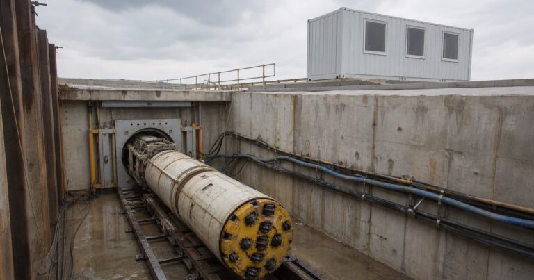
A microtunnel boring machine is a remote-controlled, closed-face unit that cuts the bore, holds the face and is pushed by a jacking frame from the launch shaft. Selecting one is a conversion exercise: drive conditions become machine attributes, and attributes become guaranteed numbers a supplier can quote. This guide covers the five subsystems, the two drive architectures, the requirement-to-attribute matrix, the RFQ inputs and the four limits where capability runs out. Every figure below is a published range that must be confirmed for the actual drive.

What Is a Microtunnel Boring Machine?
A microtunnel boring machine (MTBM) is a remote-controlled, closed-face cutterhead unit that is pushed through the ground by hydraulic rams in the launch shaft; it never propels itself. Published machine ranges run from roughly 30 in to 114 in outside diameter, which is why the operator works from instrument readings in a surface control container rather than from inside the tunnel.
In our equipment reviews, the most common misunderstanding is that the machine is self-propelled or steered from inside. The jacking frame behind the pipe string provides every tonne of jacking force, and the machine’s job is to cut the ground cleanly enough that the string can follow. That split of responsibility is what makes the launch shaft, the thrust wall and the jacking frame as much a part of the machine specification as the cutterhead. Machine selection therefore begins with the drive conditions, not with a machine catalog.
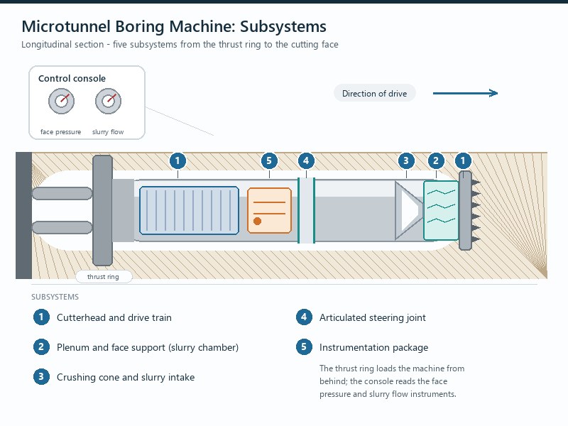
The Five Subsystems of an MTBM, and What Each One Does
Machines from different suppliers look different, but every microtunneling machine has to solve the same five problems. Reading a machine specification as five subsystems rather than one machine makes the selection decision much clearer, because each subsystem has its own limiting condition.
Subsystem 1: Cutterhead and drive train
The cutterhead is the cutting structure and the drive train is what turns it. Smaller machines use a center drive: a single motor driving a planetary gearbox coupled to a shaft at the center of the machine. Larger machines use a peripheral drive, with interior motors on the periphery of the gear ring driving pinions on a slewing bearing.
The practical difference is torque and re-tooling. Peripheral drive machines are described as offering higher power and torque for larger pipe installations, with selectable low, medium and high torque settings for changeable geology. That matters because torque, not thrust, is usually what stalls a drive in sticky clay or mixed face.
Subsystem 2: Face support and the plenum
Face support is the defining feature of the method. The machine balances thrust pressure and slurry against the groundwater and earth pressure at the face, so the ground in front of the cutterhead does not run into the machine. On a slurry microtunneling drive the support medium is a bentonite-based suspension circulated in a closed loop from the surface; on earth-pressure-balance (EPB) machines the excavated soil is conditioned and held as a plug. Water-industry specifications require control fine enough to adjust to changing face conditions and to hold pressure within about 10% of the required value.
This is why the machine carries face pressure gauges as a minimum instrument. If face pressure falls, ground and water enter and the surface settles; if it rises, the ground can heave or the slurry can escape along the alignment.
Subsystem 3: Articulated steering and roll control
Steering is mechanical: an articulated steering joint, adjusted by three points along the machine, extends and retracts to change direction, and hydraulically activated dirt wings (fins on the machine body) resist the torque roll the rotating cutterhead induces. Without roll control, the machine gradually rotates and the guidance target moves out of the laser beam.
Subsystem 4: Spoil intake, crushing cone and slurry circuit
Cut material is forced into a crushing cone that pulverizes it into particles small enough to travel in the slurry return line. Machines of this class are described as able to crush cobbles up to about 28% of the machine outside diameter. High-pressure jetting nozzles break down clay and silt and clean the crushing cone to prevent it clogging the slurry intake.
On a slurry microtunneling spread the fluid is moved by feed, booster and return pumps, with the feed pump at the surface near the tanks or separation plant, a booster pump often carried in the machine, and the return pump at the bottom of the launch shaft. Variable frequency drives regulate them from the control container. On drives we have supported, slurry intake blockage, not cutting capacity, was the most frequent cause of a stalled advance in clay.
Subsystem 5: Instrumentation
A machine that cannot be seen has to be measured. The instrument package on a typical console reports pitch, yaw, rotation, torque, jetting, jacking thrust and advance rate, ground pressure at the face, and slurry flow and pressures. It also shows cutterhead position, air and drive-motor temperatures. Manufacturers describe logging on the order of 100 data points, which is what makes an as-built record possible after the drive.
| Instrument | What it tells the operator | What it protects against |
|---|---|---|
| Face pressure gauges | Whether support pressure matches the ground and water pressure | Settlement, heave and loss of face |
| Cutterhead speed, direction, torque and thrust | How hard the machine is working for the advance it is achieving | Over-thrusting, tool damage and motor overload |
| Slurry flow and pressure gauges (slurry machines) | Whether cuttings are being removed and the circuit is balanced | Blockages and loss of transport capacity |
| Screw speed and pressure drop (EPB machines) | Whether the soil plug is holding pressure | Face loss through uncontrolled spoil discharge |
| Advance rate and excavated volume per pipe | Whether the volume removed matches the theoretical bore | Over-excavation and unrecorded ground loss |
| Cutterhead door aperture status where fitted | Whether the face opening position is as intended | Opening the face unintentionally in running ground |
Center Drive vs Face-Access Peripheral Drive: Why Diameter Decides It
The two drive architectures answer different diameter ranges. Center drive gives a compact drive train for smaller bores; peripheral drive frees the center of the machine for an access door so tooling can be changed from inside. Center drive covers the smaller end of the published 30 in to 114 in outside-diameter range, and the access-door peripheral architecture takes over at the larger base diameters.
Face access is the decisive factor on a long or abrasive drive. Some cutterheads are designed to hold tooling integrity for the whole drive; others need the option to replace tooling underground, which requires a machine with face access so the cutterhead can be reached from inside the machine. In some conditions, ground stabilization or hyperbaric pressurization is required to perform that maintenance, and a machine without an access route simply has to finish the drive with the tooling it launched with.
| Attribute | Center drive | Face-access peripheral drive |
|---|---|---|
| Base sizes in the published range | Lower end of the published 30 in to 114 in (about 760 to 2,900 mm) range | Upper end of the published 30 in to 114 in (about 760 to 2,900 mm) range |
| Drive train | One motor, planetary gearbox, central drive shaft | Interior motors on the gear ring periphery, pinions on a slewing bearing |
| Power and torque | Adequate for smaller pipe installations | Higher power and torque; selectable low, medium and high torque |
| Tooling access | No internal face access route | Access door at the cutterhead with back-loaded tooling mounts |
| Where it fits | Shorter drives, smaller diameters, benign ground | Large diameters, extended drives, abrasive or mixed ground |
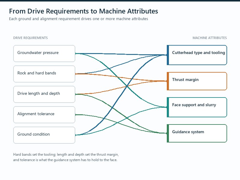
How Do You Convert a Drive Into a Machine Specification?
Start from the drive and work forward, because every machine attribute traces back to a physical condition the drive imposes. On drives we have supported, projects that skipped this step ended up negotiating machine changes after award, which is the most expensive time to change anything.
- Product pipe diameter and outside diameter. This sets the minimum bore and therefore the machine class. It also sets the annular gap the machine’s gauge cutters (the outer-edge cutters that overcut the bore beyond the pipe outside diameter) must create.
- Ground conditions by interval. Sand, gravel, silt, clay, cobbles, rock and mixed face drive the cutterhead and tooling choice, and abrasiveness drives the wear protection.
- Groundwater and permeability. These decide whether the machine must hold a pressurized face and whether a slurry or earth-pressure system is appropriate.
- Drive length and alignment. Length and curvature decide the required jacking force and torque, the intermediate jacking station spacing, and which guidance system will hold tolerance to the end of the drive.
- Tolerance. A gravity sewer line and a casing pipe carry very different allowable deviations, and the tighter requirement propagates into guidance choice and steering authority.
- Shaft geometry and site constraints. Shaft size limits the jacking frame stroke and the space available for the control container, power pack and separation plant.
En résumé : a machine specification is only complete when it also states what will happen if the ground differs from the prediction – which means cutterhead intervention, spares and a re-tooling plan are part of the specification, not afterthoughts.
MTBM Selection Matrix: Requirement to Machine Attribute
The matrix below is the working version we use for machine selection. Each row converts a project requirement into something a supplier can quote against.
| Project requirement | Machine attribute it drives | What to ask the supplier for |
|---|---|---|
| Water-bearing, unstable ground | Closed face with active support pressure | Face pressure control range, accuracy of control and failure mode on loss of power |
| Hard rock or cobbles | Rock or mixed-ground cutterhead with disc cutters | Disc size and spacing, expected cutter consumption and change-out plan |
| Abrasive sand and gravel | Wear protection on cutterhead, cone, tools and slurry lines | Hard-facing specification, wear-plate locations and wear limits |
| Long drive | Thrust and torque margin, lubrication provision, interjack compatibility | Guaranteed thrust and torque at the stated diameter, and interjack interfaces |
| Curved alignment | Articulated steering authority and guidance type | Minimum radius, joint deflection allowance and guidance system for curves |
| Tight tolerance | Guidance system, inclinometers and steering resolution | Achievable line and grade tolerance, and how it is verified during the drive |
| Small launch shaft | Machine and jacking frame geometry, pipe segment length | Machine length, minimum shaft dimensions and pipe handling method |
Applies to: owners, contractors, bidders and EPC firms selecting a machine at tender stage. Not applicable where: the method or machine family is still being chosen, or the ground model is not yet defined. Every value here is a typical published range and must be confirmed per drive by the machine supplier and a competent engineer.
What to Write Into the RFQ So Bids Are Comparable
An RFQ that lists guaranteed, checkable numbers is what makes bids comparable; a qualitative description of the drive is what makes them incomparable. Most microtunneling equipment disputes trace back to an RFQ that described the drive qualitatively.
- Guaranteed thrust and torque at the specified diameter, not a family maximum taken from a larger machine.
- Face pressure control band, and confirmation that control can be maintained within about 10% of the required pressure through the expected ground.
- Cutterhead configuration, tooling list and spares allowance for the predicted ground, expressed as quantities per drive length.
- Intervention capability: whether the machine has an access door, what tooling can be changed from inside, and whether the change is made under free air or compressed air.
- Guidance system with the achievable tolerance, the audit method, and the instrument update interval.
- Jacking frame thrust, stroke and grouping, with the number and arrangement of rams and the calibrated pressure gauges fitted so jacking force can be read at any time during the drive.
- Slurry or spoil handling requirements the machine imposes – the controlling constraint on any slurry microtunneling drive – including required flow rate, permitted particle size at the intake, and pressure-sensor provision on feed and discharge lines.
- Commissioning and acceptance tests, including what is demonstrated before shipment and what is re-demonstrated in the shaft.
Where Machine Capability Quietly Runs Out
A machine rarely fails at the limit printed on its datasheet; it fails where a drive requirement was never converted into a number. Four limits matter most: thrust margin, torque margin, tooling life and guidance reach.
- Thrust margin against friction. Pipe Jacking Association empirical guidance puts jacking friction at 0.5 to 2.5 t per square meter of external circumferential area, reducible to about 0.1 t per square meter with lubricant injection.
- Torque margin in sticky ground. In clay, the binding constraint is keeping the cutterhead turning and the intake clear, not raw cutting capacity.
- Tooling life against drive length. Tool consumption is a function of abrasiveness and drive length, and the answer is decided at specification stage, when the access door is either ordered or not. Tooling selection is covered in our cutterhead and cutting-tools guide.
- Guidance reach against alignment. In our equipment reviews, line-of-sight systems are weakened by tunnel refraction and diffraction and cannot be configured for curved alignments.
En résumé : a microtunnel boring machine is selected by arithmetic, not preference.
Points clés à retenir
- A microtunnel boring machine cuts, supports the face, steers and is pushed – it never propels itself; the jacking frame provides all forward force.
- Published machine ranges run from roughly 30 in to 114 in outside diameter, with center drive at the smaller end and face-access peripheral drive at the larger end.
- Face support and control within about 10% of the required pressure is the defining capability, and it is demonstrated through face pressure instruments.
- Machine selection is a conversion exercise: requirement to attribute to a quoted, guaranteed number.
- Thrust margin, torque margin, tooling life and guidance reach are the four limits that decide whether the machine finishes the drive.
- Every figure in this guide is a typical published range and must be confirmed for the actual drive by the supplier and a competent engineer.
Questions fréquemment posées
How does an MTBM differ from an open-face pipe jacking machine?
An MTBM supports the face continuously and is steered remotely, while an open-face machine excavates without pressure control. That continuous face support is what allows a machine to work below the water table in unstable ground. An open-face or auger machine relies on the ground standing up on its own, so it suits dry, stable soils and short drives.
What diameter range do microtunnel boring machines cover?
Published machine ranges run from roughly 30 in to 114 in outside diameter. Smaller machines are usually center drive, and larger machines move to a peripheral drive architecture with face access. The product pipe diameter, not the machine, is the constraint the designer usually starts from.
How much thrust does an MTBM jacking frame need?
A jacking frame is built with cylinders delivering up to about 1,200 t of thrust and is sized to the drive, not to the machine’s maximum. Required thrust follows the friction along the pipe string, which published empirical guidance puts at 0.5 to 2.5 t per square meter of external circumferential area, falling to as little as 0.1 t per square meter with good lubrication. The launch shaft and thrust wall must be designed for the same number.
Can a microtunnel boring machine handle rock?
Yes, with the right cutterhead and tooling. Rock cutterheads carry disc cutters and bucket scrapers, mixed-ground cutterheads blend disc cutters with carbide-tipped teeth and chisel teeth, and machines of this class are described as able to crush cobbles up to about 28% of outside diameter. The real constraint is usually tool wear and how the machine will be re-tooled if the drive needs it.
Why does a machine need face access?
Face access is the only way to replace worn tooling on a long or abrasive drive. A peripheral drive machine with an access door and back-loaded tooling mounts lets crews change tools from inside the machine, sometimes under compressed air where groundwater is present. A machine without an access route has to finish the drive with the tooling it launched with.
What information does a supplier need to size a machine?
Ground conditions, drive length, alignment, groundwater, product pipe and the shaft layout. Add the geotechnical report, the required tolerance, the expected advance rate, the spoil and slurry handling plan, and the launch and reception shaft dimensions. Suppliers size the machine from those inputs, so a vague enquiry usually returns a vague machine.
How JSW Supports MTBM Selection and Delivery
JSW is a pipeline engineering and construction company that executes trenchless crossings with its own crews and equipment. Our scope covers construction par microtunnelage, technologies sans tranchée, HDD crossing services et services d'installation de pipelines, and we support owners at the stage where the machine is still a specification rather than a signed order.
Because we run our own microtunneling spreads, our equipment recommendations carry the same accountability as the drive – which is why owners bring us the specification before the order, not after.
- Requirement-driven machine selection: we start from the geotechnical report, alignment and shaft layout, then derive the machine attributes and quote against guaranteed numbers.
- Intervention planned up front: cutterhead access, tooling spares and change-out strategy are decided at specification stage, not when the drive slows down.
- Données de processus pouvant faire l'objet d'un audit : face pressure, thrust, torque, advance rate and guidance readings are recorded so ground behavior can be reviewed against prediction.
- Certified delivery: our trenchless work is delivered under ISO 9001:2015, ISO 14001:2015 and ISO 45001:2018 certified management systems.
Not sure which machine class your drive actually needs? Send your geotechnical report extract, drive length, alignment, product pipe diameter and shaft dimensions for a free technical review. Our engineers respond with a scoped machine recommendation and an indicative budget range.





































 English
  Arabic
  Russian
  Spanish
  French
  Vietnamese
  Polish
  Thai
Thai  Indonesian
  Turkish
  Portuguese