
Les défauts de soudure des conduites sont les discontinuités qui entraînent le rejet d'une soudure circonférentielle ou une fuite en service ; les plus courants sont la porosité, les inclusions de scories, le manque de fusion, la pénétration incomplète et la fissuration de la soudure.
Vous pouvez les prévenir en validant votre procédure de soudage, en contrôlant le stockage des consommables et la propreté des joints, en soudant dans les limites des paramètres validés et en vérifiant chaque soudure à l'aide des essais non destructifs appropriés. Ce guide explique comment se forme chaque défaut de soudure courant, pourquoi il survient, comment le prévenir, comment les inspecteurs le détectent, dans quels cas un défaut est acceptable, et comment les soudures défectueuses sont réparées conformément à la réglementation.
Points clés à retenir
- Sept types de défauts de soudure prédominent dans les réparations sur site : la porosité, les inclusions de scories, les défauts de fusion, les racines non remplies, les rainures de base, les fissures et les irrégularités de surface telles que les projections et les traces d'arc.
- La porosité et les scories piégées sont principalement dues à la contamination et à un nettoyage insuffisant entre les passes ; les défauts de fusion et les racines non remplies sont principalement dus aux paramètres et à la technique ; les fissures sont dues aux contraintes, à l'hydrogène et au confinement.
- La spécification de procédure de soudage (WPS) constitue une garantie de qualité : les soudures réalisées dans les limites de ses paramètres produisent rarement des défauts justifiant un rejet.
- Les fissures sont toujours considérées comme un défaut ; la porosité, les scories piégées et les rainures d'épaulement sont évaluées par rapport aux limites dimensionnelles prévues par la norme, qui dépendent de l'épaisseur de la paroi.
- L'inspection fait partie intégrante de la prévention : contrôles visuels de chaque soudure, radiographie ou ultrasons pour vérifier l'intégrité volumétrique, contrôle par particules magnétiques pour détecter les fissures au niveau du talon, et mise en attente de 48 heures pour détecter d'éventuelles fissures à froid différées.
- Chaque réparation fait l'objet d'un nouveau contrôle selon la norme 100%, selon les mêmes critères d'acceptation que ceux applicables à la soudure d'origine.
Aperçu des données clés : contrôles de la qualité des soudures
Ce sont les valeurs de terrain sur lesquelles nos équipes s'appuient pour chaque intervention. Chaque chiffre est indiqué dans ce guide et renvoie à la norme ou à la pratique de terrain mentionnée dans la colonne « Base » ; le tableau sert ainsi de référence rapide lors de la planification des inspections.
| Paramètres | Valeur | Contexte | Base |
|---|---|---|---|
| Cuisson d'électrodes à faible teneur en hydrogène | 300-400 °C | Avant utilisation | API 1104 / fabricant |
| Maintien de la tige dans le four | 120-150 °C | Entre deux utilisations | Fabricant |
| Limite d'exposition pour les bidons ouverts | 4 heures | Après avoir sorti le plat du four | Fabricant |
| Préchauffage de l'acier au carbone | 100-150 °C | Risque de condensation / règle de terrain | WPS |
| Seuil de pare-brise | Environ 16 km/h | Protection au CO₂ | Stage sur le terrain |
| Contrôle différé de la fissure avant le contrôle non destructif final | 48 heures | Articulations sensibles à l'hydrogène | API 1104 / cahier des charges du projet |
| Limite d'acceptabilité de la rainure de la pointe | 1/32 de pouce (0,8 mm) | Le mur restant s'intègre parfaitement au design | API 1104 |
Quels sont les défauts de soudage de canalisations les plus courants ?
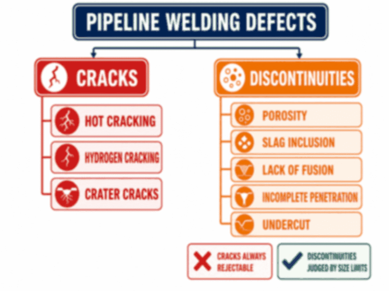
Les défauts qui entraînent le renvoi des soudures pour réparation se répartissent en deux catégories : les fissures et les discontinuités. Les fissures comprennent les fissures de solidification, les fissures à froid différées et les fissures de cratère ; les discontinuités comprennent la porosité, les inclusions de scories, les défauts de fusion, les racines non remplies, les rainures d'angle et les irrégularités de surface telles que les projections et les marques d'arc.
Chaque famille a ses propres motivations, ses propres mesures de prévention et ses propres méthodes de dépistage ; c'est pourquoi chacune d'entre elles fait l'objet d'une rubrique spécifique ci-dessous.
Dans le cadre des programmes de réparation menés par nos équipes pour le compte des exploitants, la porosité et les scories piégées ont représenté à elles deux environ la moitié des rejets radiographiques constatés sur ces projets, tandis que les défauts de fusion et les racines non remplies ont constitué la majeure partie des réparations critiques au niveau de la zone de la racine.
Cette tendance correspond à l'expérience générale des prestataires spécialisés dans l'inspection des conduites, et c'est pourquoi nos équipes, qui possèdent des qualifications de soudeurs et des certifications de procédures conformes aux normes API 1104 et ASME B31.4/B31.8, consacrent autant de temps au nettoyage et à la technique qu'aux défauts eux-mêmes.
| Famille de défauts | Là où il se forme | Cause principale | Prévention primaire | Détection primaire | Acceptation |
|---|---|---|---|---|---|
| Porosité | Weld metal | Gas from contamination, damp consumables, lost shielding | Clean bevel, dry electrodes, shield from wind | RT, VT | Size-limited; clusters/wormholes reject |
| Slag inclusion | Between passes, root | Poor interpass cleaning, low current | Clean each pass, use adequate current | RT, UT | Size-limited vs wall thickness |
| Lack of fusion | Bevel side, interpass boundary | Low heat input, wrong angle, contamination | Correct parameters and technique | UT, RT | Rejectable in girth welds |
| Incomplete penetration | Root of the joint | Closed root gap, thick land, low root current | Fit-up control, root pass technique | RT, UT | Rejectable in girth welds |
| Undercut | Weld toes | High current, long arc, fast travel | Parameter and technique control | VT, MT | Up to 1/32 in (0.8 mm) if wall OK |
| Weld cracking | Weld metal, heat-affected zone | Stress, hydrogen, restraint, contamination | Preheat, low-hydrogen consumables, crater fill | MT, UT, RT | Always rejectable |
| Spatter and arc strikes | Surrounding pipe surface | Wrong parameters, poor grounding | Parameter and ground control | VT | Cosmetic; clean per spec |
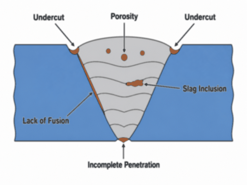
Figure 1. A girth weld cross-section shows where each common welding defect forms: toe grooves at the surface, cavities and trapped flux inside the weld metal, fusion failure at the bevel side, and an unfilled root.
What Causes Welding Defects in Pipelines?
Pipeline welding defects are rarely random. Nearly every defect traces back to one of five root causes: contamination, consumables, parameters, technique, and environment, with joint fit-up as a sixth factor because poor geometry makes every other control harder to hold.
- Contamination: rust, oil, paint, moisture, and water on the bevel supply the gas that makes porosity and the impurities that trap slag.
- Consumables: damp electrodes, expired shielding gas, and wrong filler metal size change both the chemistry and the heat input of the weld.
- Parameters: current, voltage, and travel speed outside the qualified window produce too much or too little heat, which drives most fusion failures, unfilled roots, and toe grooves.
- Technique: travel angle, weave width, arc length, and crater fill are under the welder’s hand and decide whether the molten pool wets the sidewall and toes.
- Environment: wind strips the shielding gas, humidity adds moisture, and low temperature increases the cooling rate that hardens the heat-affected zone.
- Fit-up: root gap, land thickness, bevel angle, and alignment that drift outside the WPS range convert a good procedure into a defective weld.
Each cause has a measurable control. Wind above roughly 16 km/h strips CO2 shielding and produces porosity, so we erect wind screens on open sites. Humidity that causes condensation, or rain on a prepared bevel, means the joint is cleaned and heated again; our field rule is a preheat temperature of 100-150 °C for carbon steel to drive off surface moisture before the first bead. Fit-up is checked with gap and land gauges on every joint, and bends produced by pipeline cold bending are measured the same way, because a bend that distorts the gap makes the girth weld start from a defect.
Weld Porosity: Causes and Prevention
Weld porosity is gas trapped in the solidifying weld metal as round or elongated cavities, and it is the most frequent rejectable discontinuity on radiographs. Scattered pores are usually cosmetic, but cluster porosity and elongated wormholes reduce the load-bearing section and are treated far more strictly.
Porosity in pipeline welding forms when gas dissolved in the molten pool cannot escape before the metal freezes. The gas comes from moisture, rust, oil, or paint on the bevel, from damp electrode coatings, from shielding gas lost to wind or hose leaks, and from travel speeds so fast that the pool freezes too quickly to release the gas.
- Scattered porosity: isolated pores spread through the weld, usually from minor contamination or slightly damp consumables.
- Cluster porosity: a dense group of pores, typically from a local contamination pocket such as a patch of rust or a water drop.
- Wormhole porosity: elongated, branching cavities that run with the solidification direction, caused by heavy gas generation and fast freezing.
- Crater porosity: pores concentrated in the weld crater at the arc stop, where gas collects as the arc is withdrawn.
Preventing weld porosity follows the gas sources. Clean the joint faces and 25 mm on each side of the bevel down to bare metal, and re-clean after rain or overnight dew. Bake low-hydrogen electrodes at 300-400 °C, hold them at 120-150 °C, and limit exposure to air to four hours.
Check gas flow and hoses before every shift, shield the arc from wind, and keep travel speed inside the WPS range. When condensation is possible, apply a preheat temperature of 100-150 °C to dry the joint and hold the temperature until the surface stays dry.
The code judges porosity by size, distribution, and wall thickness: small scattered pores within the limits are acceptable, while cluster porosity, elongated wormholes, and surface porosity above the limits are rejectable. In our own radiography reviews, most porosity rejections traced to one cause: a bevel cleaned hours earlier, rained on, and welded without re-cleaning. The fix cost nothing except a second pass with the grinder.
Slag Inclusion: Causes and Prevention
Slag is the non-metallic flux residue trapped inside the weld metal or between passes, left behind by stick (SMAW) or flux-cored (FCAW) welding. It shows up on radiographs as dark, irregular indications and on fracture surfaces as brittle inclusions that act as stress concentrators.
It gets trapped when the previous pass is not cleaned completely, when the current is too low for the slag to float out, when the joint is too narrow for the welder to reach the corners, or when the technique lets molten slag flood ahead of the arc and freeze into the weld. The root pass and the toes of each pass are the places it hides best.
Prevention is a cleaning discipline. Remove all slag after every pass with a chipping hammer and power brush, including the weld toes and the corners of the bevel, where it clings hardest. Weld with the current and travel speed from the WPS so the slag pool trails the arc instead of freezing in front of it. On narrow joints, open the bevel angle or use a smaller electrode for the fill passes.
Trapped flux is more than a cosmetic problem: it concentrates stress and can initiate cracking in service, especially in sour pipelines where hardness control already matters. The code limits its size based on wall thickness, and any inclusion that reduces the effective wall below the design value is rejectable. Our site rule makes interpass cleaning a quality gate: no pass is deposited until the previous pass has passed visual inspection, because a slag line buried in the weld costs far more to cut out than to prevent.
Lack of Fusion: Causes and Prevention
Lack of fusion is the failure of weld metal to fuse with the base metal or with a previous pass, leaving a planar, crack-like interface inside the joint. It forms at the bevel sidewall, at the root, or between passes, and it is the most dangerous of the discontinuity defects because a planar gap propagates under fatigue and pressure cycling.
It happens when the heat input is too low to melt the base metal, when the travel angle points the arc away from the sidewall, when the surface is contaminated, when the electrode is too large for the joint, or when magnetic arc blow pushes the arc off the bevel. It is a technique and parameter defect, which is why it clusters on difficult positions and on long root runs.
Prevent it by welding inside the qualified parameter window: adequate current for the joint size, a travel angle that keeps the arc on the leading edge of the pool, slower travel where the WPS calls for it, and complete cleaning of the joint faces. Use a weave that reaches both sidewalls on fill passes, and correct magnetic arc blow by repositioning the ground clamp instead of fighting the arc.
Ultrasonic testing detects the tight planar gap far more reliably than radiography, because the closed interface reflects sound sharply while the X-ray beam passes straight through it. The code treats it as rejectable in girth welds. In the hundreds of girth weld programs we have completed, it appeared most often at the 5G and 6G root and sidewall, exactly where the welder has the least visibility and the most constraint.
Incomplete Penetration: Causes and Prevention
Incomplete penetration is the root of the joint left unfilled, so the weld does not extend through the full wall thickness. It concentrates the entire service stress at the root notch and is rejectable in girth welds.
It forms when the root gap is too small or the land too thick for the arc to reach the root, when the root current is too low, when the root pass travels too fast, or when the backing strip or internal line-up clamp pulls the joint out of alignment. On open-root pipe welding, the root pass is where penetration is won or lost.
Prevention starts at fit-up. Measure the root gap and land on every joint with a gauge, hold alignment with an internal line-up clamp, and set the root current at the top of the WPS range for the joint position. Weld the root with a controlled technique that melts through the land, and inspect the root pass visually from the inside or with a mirror before the fill passes go in, when correction is still cheap.
In our experience, most root gaps on automated jobs trace to fit-up drift: the gap closed up over a long weld run and no one re-measured it. The same discipline applies to pipeline construction tie-ins, where fit-up is measured once and assumed to hold. It does not hold; measure every joint.
Undercut: Causes and Prevention
Undercut, also called a toe groove or undercutting, is the groove melted into the pipe surface along the weld toe that the weld metal did not fill, leaving a sharp notch at the edge of the bead. It reduces the load-bearing wall and creates a stress raiser exactly where fatigue cracks start.
It forms when the current is too high, the arc is too long, the travel speed is too fast, the electrode angle leaves the toes, or the weave is so wide that the toes solidify before the molten metal flows back. Vertical-up welds on the 5G and 6G positions are the classic sites because gravity drains the pool from the toes.
Prevent it by using the WPS current, keeping a short arc, holding the correct travel angle, limiting weave width to about two to three times the electrode diameter, and pausing briefly at each toe so the pool fills the groove. Reduce current slightly when the groove appears instead of speeding up the pass.
Visual testing catches most toe grooves, and magnetic particle testing finds the tight notches that the eye misses. The code permits a toe groove up to 1/32 in (0.8 mm) deep where the remaining wall still meets the design thickness, and requires repair when it is deeper. It is the weld defect our inspectors check first, because it is the easiest one to see and the easiest one to leave behind on a rushed weld.
Weld Cracking: Hot Cracking, Cold Cracking, and Crater Cracks
Cracks are the most dangerous discontinuity defects because they are sharp, planar, and grow in service. Under API 1104 (Section 9, acceptance criteria) and ASME B31.4/B31.8, any crack in a girth weld is rejectable regardless of size, so the only question is prevention. Three crack families matter in pipeline work: solidification cracking, delayed cold cracking, and crater cracks.
Hot Cracking (Solidification Cracking)
Hot cracking forms in the weld metal while it is still solidifying, when sulfur and phosphorus segregate to the centerline and a shrinking, restrained bead tears along the liquid film. It appears immediately after welding, usually on the bead centerline, and is favored by wide beads, high restraint, and filler metal with high impurity levels.
Prevent it by using filler metal with low sulfur and phosphorus, balancing the bead width-to-depth ratio to about 1:1, controlling restraint where the design allows, and preheating to slow the cooling rate. Crater cracks are the arc-stop variant of the same mechanism, where the pool shrinks without filler metal; they are prevented by filling the crater before breaking the arc, either manually or with the crater-fill function on automatic welding power sources.
Cold Cracking (Hydrogen Cracking)
Cold cracking, also called hydrogen cracking or hydrogen-induced cracking, is the delayed crack in the weld metal or heat-affected zone that appears hours to days after welding, driven by diffusible hydrogen, a hard microstructure, and tensile stress acting together. It is prevented with low-hydrogen consumables, preheat, interpass control, post-heat, and inspection on a 48-hour delay, and it is covered in detail in our separate guide to hydrogen cracking in pipeline welding.
In-service welds such as hot tapping add a second set of constraints: the pipe is full and under pressure, so burn-through and rapid cooling of the weld raise both porosity and cold cracking risk. Those jobs are executed with special procedures, lower heat input limits, and often with hot tapping equipment sized and qualified for the exact line condition.
Reheat Cracking and Lamellar Cracking
Reheat cracking occurs during post-weld heat treatment or high-temperature service in thick-wall, creep-resistant steels, and lamellar cracking tears the parent plate in the through-thickness direction under high restraint. Both are rare in ordinary carbon steel pipelines and are controlled by material selection, joint design, and qualified heat treatment procedures rather than by daily field technique.
The practical message is that cracks are prevented, not repaired cheaply. When a crack is found, it is cut out completely, the removal is verified, and the joint is re-welded and re-inspected; a repair that hides a crack tip guarantees it will return.
How to Prevent Pipeline Welding Defects: 7 Field Rules
Prevention is a system, not a checklist, and most welding defects can be prevented with the seven rules below working together. Each rule is written into the qualified procedures our crews use on pipeline construction, maintenance, and repair jobs, and skipping one multiplies the risk of the others.
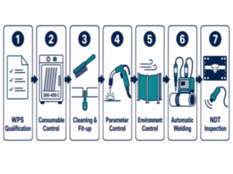
Figure 2. A seven-stage field workflow prevents pipeline welding defects from procedure qualification to final inspection.
1. Qualify the WPS and Weld Inside It
The welding procedure specification fixes the process, consumables, current range, travel speed, preheat, interpass temperature, and positions, and a WPS qualified to API 1104 has already proven the combination produces sound welds. Our crews treat any parameter reading outside the WPS range as a stop-work event: the weld is halted, the cause is found, and the joint is evaluated before work resumes. The procedure is not a suggestion; it is the baseline that makes every other rule measurable.
2. Control Consumables From the Oven to the Arc
Consumables carry hydrogen and moisture directly into the weld. Bake low-hydrogen electrodes at the manufacturer’s temperature, typically 300-400 °C, hold them in rod ovens at 120-150 °C, and limit opened-can exposure to four hours. Check shielding gas flow and hoses before each shift, and store filler wire and fluxes in dry, sealed conditions.
In our welding department, opened electrode cans are marked with the time they left the oven, and a rod exposed too long is scrapped, not reused. The rule costs almost nothing and eliminates the largest single source of porosity.
3. Clean, Dry, and Fit the Joint
Clean the joint faces and 25 mm on each side down to bare metal, dry the bevel with a preheat temperature of 100-150 °C where condensation is possible, and verify root gap, land, bevel angle, and alignment with gauges on every joint. Internal line-up clamps hold alignment through the root pass, and misalignment beyond the WPS allowance is corrected before welding, not during it.
Fit-up includes the fittings and bends that feed the weld line. A bend made with pipeline cold bending that distorts the gap or wall thickness in the weld zone starts the girth weld from a defect, so we measure the weld prep on every bend as carefully as on every straight pipe joint.
4. Weld With Correct Parameters and Technique
Set current, voltage, and travel speed from the welding procedure specification, hold the travel angle that keeps the arc on the pool edge, limit weave width, fill craters, and match technique to the position. Root passes on the 5G and 6G positions deserve the most attention because they have the least visibility, and they are where the pipeline welding positions differ most in difficulty.
Technique errors do not announce themselves until the film or the scan, so we verify the root pass visually before the fill passes. Correcting a root defect at that point is a grinder job; correcting it after the weld is complete is a cut-out job, which typically costs several times the original weld pass and adds days to a tie-in schedule.
5. Control the Environment
Wind strips shielding gas and produces porosity; humidity and rain add moisture; cold increases cooling rate and hardness. Erect wind screens above roughly 16 km/h, stop welding in rain, preheat to dry the joint, and raise the temperature in cold weather per the WPS.
On a recent 36-inch tie-in on a coastal project, humidity was high enough that condensation formed on the bevel within minutes of cleaning. We heated the joint and kept it hot until the surface stayed dry, checking the temperature with an infrared gun before every pass. The radiography came back clean; the discipline is what made it clean.
6. Use Automatic Welding for Consistency
Automatic pipeline welding removes the human variables of travel speed, arc length, and weave width, which are the variables behind most fusion failures and toe grooves. Dual-torch systems on large-diameter pipe hold the parameters within tight tolerances and log them for every weld, giving inspectors a record instead of a memory.
Automatic welding does not replace the WPS or the other six rules; it makes them easier to hold. On our large-diameter projects, we pair automatic pipeline welding with manual root passes where the WPS calls for them, and the parameter logs go into the weld book with the radiographs. If automatic welding is new to your project, our welding engineers will review your WPS and NDT requirements and recommend the right process, usually within 24 hours.
7. Inspect Every Weld, Hold the High-Risk Ones
Welding inspection is the last prevention rule because it catches what the first six missed. Visual testing is applied to every weld, radiography or ultrasonic testing per the code and contract, magnetic particle testing on surface-critical toes, and a 48-hour hold before final NDT where hydrogen cracking is a risk. Hardness surveys verify the microstructure on high-strength or sour-service welds.
The inspection result feeds back into the process: a defect pattern from the first welds of a run changes the next welds, not just the rejected ones. That feedback loop is why our rejection rates drop across a project as the crew, the procedure, and the inspection settle into each other.
How Do You Detect Pipeline Welding Defects? NDT Methods Compared
The different types of welding defects each have a detection method that finds them best, and a welding inspection program uses several methods together because no single one sees everything. Visual checks are the baseline, volumetric methods look inside the weld, and surface methods find toe and surface cracks.
| NDT method | Defects it detects | Strengths | Limites |
|---|---|---|---|
| Visual testing (VT) | Toe grooves, spatter, arc strikes, bead profile, surface porosity | Fast, cheap, applied to every weld | Surface only |
| Radiographic testing (RT) | Porosity, entrapped slag, unfilled roots, gross fusion failures | Permanent film or digital record | Low sensitivity to tight planar cracks |
| Ultrasonic testing (UT, PAUT) | Fusion failures, cracks, slag, unfilled roots, wall loss | Excellent for planar defects; phased array adds imaging | Requires skilled operators and couplant |
| Magnetic particle testing (MT) | Surface and near-surface toe cracks | Fast, sensitive to tight surface cracks | Ferromagnetic materials only |
| Penetrant testing (PT) | Surface-opening defects and porosity | Simple, works on any material | Surface only; requires clean surface |
Cross-country pipeline girth welds are typically inspected by radiographic testing or ultrasonic testing at the code-required percentage, with MT on the toes of high-risk welds and visual testing on every joint. Our full inspection sequence, including hold times and acceptance rules, is covered in our pipeline welding inspection checklist. Not sure which NDT combination your code and contract require? Send us your project specification for a free inspection plan review.
When Is a Pipeline Welding Defect Acceptable?
Acceptance is decided by the code named in the contract, usually API 1104 Section 9 for cross-country pipelines, with ASME B31.4 and B31.8 for liquid and gas transmission systems, and by the project specification on top of the code. Welding inspection does not judge by eye; every indication is compared against the code’s size limits.
- Cracks: never acceptable in any form, any size, or any location.
- Porosity: small scattered pores within the code limits are acceptable; cluster porosity, wormholes, and surface porosity above the limits are not.
- Entrapped slag: limited by size relative to wall thickness; inclusions that reduce the effective wall below design are rejectable.
- Fusion failures and unfilled roots: rejectable in girth welds because both act as planar stress raisers at the root and sidewall.
- Undercut: acceptable up to 1/32 in (0.8 mm) deep where the remaining wall meets design; deeper grooves are repaired.
- Spatter and arc strikes: cosmetic; cleaned per project spec, not a structural acceptance item.
The practical rule we give every inspector and welder: when in doubt, the indication is measured against the code table, not argued about on site. Our NDT interpreters mark every indication against the acceptance criteria in the inspection procedure, and the weld book records the disposition, so an accepted weld is accepted on paper, not on memory.
How Are Defective Pipeline Welds Repaired?
Defective pipeline welds are repaired in two ways, depending on the defect. Surface defects such as toe grooves, spatter, and shallow surface porosity are ground and blended to a smooth contour and verified with MT or penetrant testing. Volumetric and planar defects require removing the complete defect, which usually means cutting out the weld and re-welding the joint.
For a cut-out, the weld is removed with a pipeline cutting machine to a clean bevel, the area is cleaned and inspected to confirm the defect is gone, and the joint is re-welded with the same qualified procedure as the original weld. The weld repair is then inspected 100% with the same non-destructive testing methods and acceptance criteria as the original, because a repair weld is a new weld with all the same risks.
A weld repair is a second thermal cycle on already-cycled material, which is why cold cracking risk rises on repaired high-strength joints and why low-hydrogen consumables and delayed inspection apply to the repair exactly as they did to the original weld. In our pipeline repair work, the failures we see are almost always from cutting out only the visible indication and re-welding over the hidden defect. Cutting out the complete defect, verifying removal, and re-inspecting 100% is not optional; it is the repair. Where a weld cannot be repaired in place, our crews can rehabilitate or replace the affected section using trenchless pipeline repair methods.
Questions fréquemment posées
What is the most common pipeline welding defect?
The most common types of welding defects in pipelines are porosity and entrapped slag. Both come from contamination and cleaning gaps rather than difficult welding conditions, and both are prevented with clean bevels, dry consumables, and thorough interpass cleaning.
What causes porosity in pipeline welding?
Porosity in pipeline welding is caused by gas trapped in the solidifying weld metal. The gas comes from moisture, rust, oil, or paint on the bevel, damp electrode coatings, shielding gas lost to wind, hose leaks, or travel speeds so fast that the pool freezes before the gas escapes.
What is the difference between lack of fusion and incomplete penetration?
Fusion failure is the failure of weld metal to bond with the base metal or a previous pass, usually at the sidewall or interpass boundary. An unfilled root leaves the root faces unjoined; both are planar, stress-raising defects and both are rejectable in girth welds.
Are cracks ever acceptable in pipeline welds?
No. Any crack in a pipeline girth weld is rejectable regardless of size or location, and because cracks grow in service, the standard response is complete removal of the cracked weld and re-welding, not acceptance.
How much undercut is allowed in a pipeline weld?
The code permits a toe groove up to 1/32 in (0.8 mm) deep where the remaining wall still meets the design thickness. Deeper grooves are repaired by grinding and blending, or by weld build-up followed by re-inspection.
What is the best NDT method for pipeline girth welds?
No single method is best; the combination matters. Radiographic testing or ultrasonic testing verifies volumetric soundness, phased array is superior for planar defects, and MT finds toe cracks on the surface. See our pipeline welding inspection checklist for hold times and acceptance rules.
Can a defective pipeline weld be repaired?
Yes. Surface defects are ground and blended; volumetric and planar defects are cut out completely and re-welded with the qualified procedure. Every weld repair is re-inspected 100% with the same NDT methods and acceptance criteria as the original weld.
Does automatic welding eliminate welding defects?
No, but it removes the human variables behind most of them: automatic pipeline welding holds travel speed, arc length, and weave within tight tolerances and logs the parameters. The WPS, consumable control, cleaning, and inspection still govern the result.
What is the difference between porosity and slag inclusion?
Porosity is gas trapped in the solidifying weld metal as round or elongated cavities, while slag inclusion is non-metallic flux residue trapped inside the weld or between passes. Porosity comes from contamination and damp consumables; slag comes from incomplete interpass cleaning and low current.
How long should you wait before NDT after welding?
Hold high-risk girth welds for 48 hours before final non-destructive testing, because hydrogen-induced cracking is delayed and can appear days after welding. The 48-hour hold is a standard project-specification requirement for joints exposed to hydrogen risk.
Where do pipeline welding acceptance criteria come from?
Acceptance criteria come from the code named in the contract, usually API 1104 Section 9 for cross-country pipelines, with ASME B31.4 and B31.8 for transmission systems. The project specification adds requirements on top of the code, and every indication is measured against the code tables rather than judged by eye.
Do automatic and manual welding differ in defect repair rates?
Automatic pipeline welding produces more consistent fusion and fewer toe defects because it removes the human variables of travel speed, arc length, and weave width. Manual welding keeps the advantage in tight positions, but its repair rates depend on welder skill and qualification, so the procedure and the inspection still decide the outcome.
Unsure which defects are hiding in your girth welds? Send us your pipe grade, wall thickness, welding process, and NDT results. Our welding engineers will review the defect pattern and confirm the prevention measures within 24 hours.
Most welding defects in pipelines are preventable. The system that eliminates the majority of field rejections is a chain of controlled inputs: clean joints, dry consumables, a qualified procedure held inside its parameter window, controlled technique, controlled environment, and inspection that feeds back into the process. Porosity and entrapped slag come from contamination and cleaning; fusion failures and unfilled roots come from parameters and technique; cracks come from stress, hydrogen, and restraint. Each family has a known cause, a known prevention, and a known detection method, and none of them survives a disciplined system for long.
In our pipeline construction, repair, and maintenance work, the joints that fail are almost always the ones where a control was skipped: a damp rod, a rained-on bevel, a fit-up that drifted, or an inspection that was rushed. The weld that passes the system is the weld that passes the years.
If you are planning pipeline construction, pipeline maintenance, repair, hot tapping, or line stopping, work with a team that treats defect prevention as routine. JSW has completed more than 1,200 hot tap and line stopping jobs and hundreds of pipeline girth weld programs across Asia, the Middle East, Africa, and South America, with welder and procedure qualifications to API 1104 and ASME B31.4/B31.8, backed by our own line of hot tapping machines, line stopping plugs, and pipeline cutting machines.
Where a line is beyond repair, our crews so handle trenchless pipeline repair, horizontal directional drilling, and microtunneling for replacement crossings. Send us your pipe grade, wall thickness, welding process, and service, and our engineers will confirm the defect prevention and inspection measures for your job and provide a quotation, usually within 24 hours





































 English
  Arabic
  Russian
  Spanish
  French
  Vietnamese
  Polish
  Thai
Thai  Indonesian
  Turkish
  Portuguese