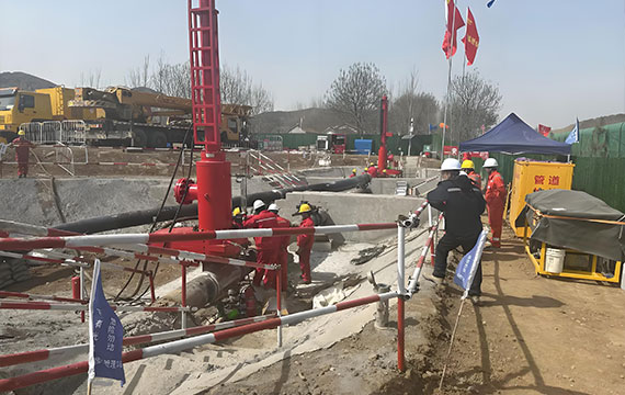
Pipeline Plug Isolation in One Minute
- Creates a temporary internal seal using mechanical or inflatable expansion
- Enables downstream maintenance, hot tapping, or repairs without system shutdown
- Must withstand differential pressure up to the pipeline’s MAOP
- Under cyclic pressure, adhesive bonding quality determines long-term reliability
Field data shows that over 70% of pipeline isolation failures are linked to improper material selection or installation—not pressure overload.
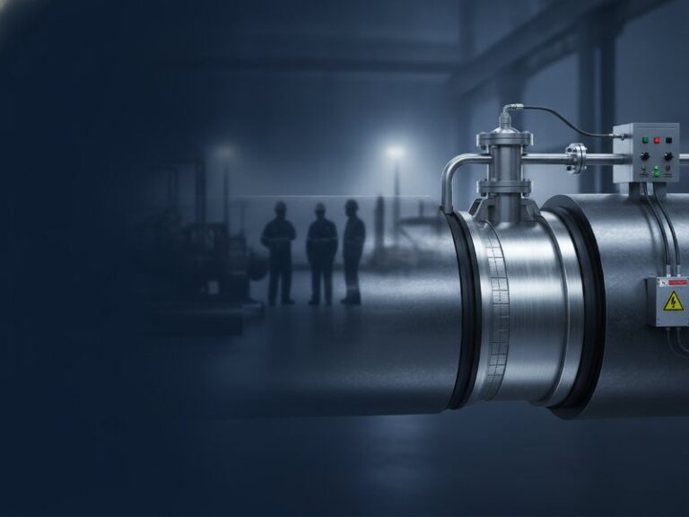
What Is a Pipeline Plug?
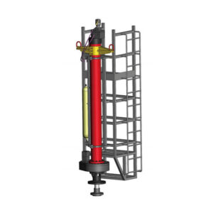
A pipeline plug is a temporary internal isolation device inserted into a pressurized pipeline to stop flow and create a safe working section without shutting down the entire system.
How Does a Pipeline Plug Work During Isolation?
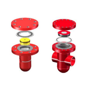
A pipeline plug isolates a section of pipe by expanding a sealing element—either through mechanical arms or pneumatic inflation—directly against the pipe’s internal wall, creating a pressure-tight barrier. It withstands differential pressure from the upstream side while allowing downstream work such as cutting, welding, or component replacement without shutting down the entire pipeline.
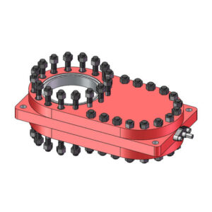
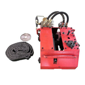
Key Components of a Typical Pipeline Isolation Plug
The table below summarizes the key components of a typical pipeline isolation plug and their functions.
| Component | Function | Material Example |
|---|---|---|
| Sealing element | Creates gas-tight seal against pipe ID | Nitrile rubber, polyurethane |
| Expansion mechanism | Applies radial force | Hydraulic cylinder or air inflation |
| Bypass valve | Equalizes pressure across plug | Carbon steel, 316 SS |
| Position sensor | Confirms full sealing | Magnetic or proximity sensor |
| Tether/retrieval system | Enables removal after isolation | Synthetic rope or steel cable |
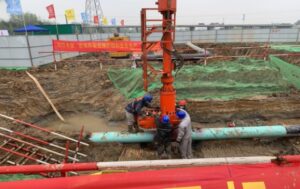
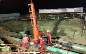
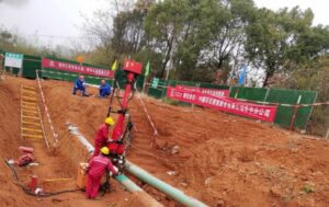
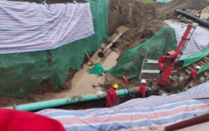
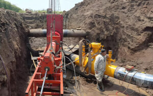
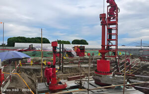
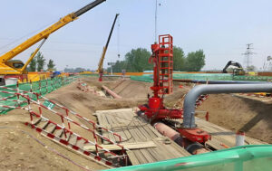
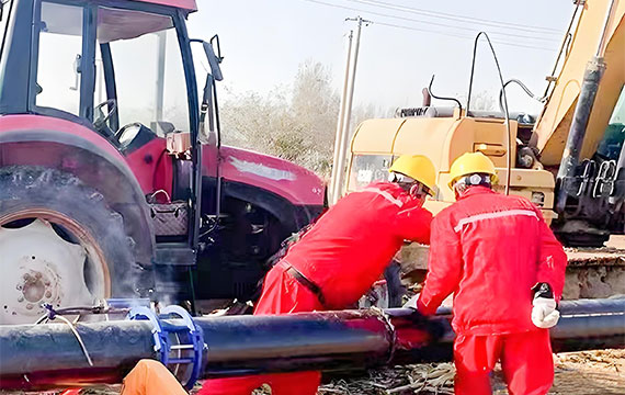
Step-by-Step: How a Pipeline Plug Is Deployed During Isolation
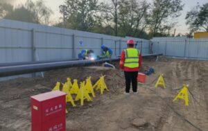
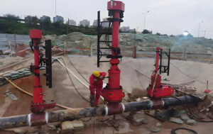
- Hot tap installation – A fitting and valve are welded to the pipeline under full operating pressure.
- Insertion – The plug is introduced through the valve into the pipe bore.
- Positioning – The plug travels to the designated isolation point, often guided by a camera or pig tracker.
- Sealing – Mechanical arms expand or inflation pressure rises (typically 1.5x line pressure) to engage the pipe wall.
- Проверка давления – A small bleed valve confirms zero flow downstream.
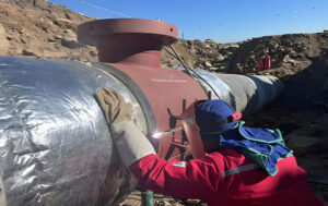
- Maintenance work – Crews open the downstream section, weld new connections, or replace failed components.
- Retrieval – The plug is collapsed and withdrawn, and the access fitting is capped.
Inflatable vs. Mechanical Pipeline Plugs: A Comparison
The table below compares inflatable and mechanical pipeline plugs across key selection criteria.
| Критерий | Надувная заглушка | Механический штекер |
|---|---|---|
| Deployment speed | Faster (minutes) | Slower (requires precise positioning) |
| Surface irregularity tolerance | High – conforms to oval or corroded pipe | Low – requires round, clean bore |
| Maximum pressure rating | Typically lower (<300 psi for larger diameters) | Higher (up to 1,480 psi / 100 bar) |
| Cyclic pressure performance | Moderate – elastomer fatigue over time | Excellent – metal-to-metal or rigid composite |
| Retrieval reliability | High – deflates completely | Requires careful collapse mechanism |
| Типичное применение | Gas distribution, water lines | High-pressure oil & gas transmission |
For cyclic pressure conditions (frequent pump starts or compressor cycling), mechanical or carbon fiber-reinforced composite plugs consistently outperform standard inflatable designs.
How Does a Pipeline Plug Perform Under Cyclic Pressure Conditions?
Under cyclic pressure, a pipeline plug’s isolation integrity depends entirely on the fatigue resistance of its adhesive layer and composite structure. Testing shows that standard glass fiber systems typically delaminate between 500,000 and 2 million cycles, while high-toughness carbon fiber systems with silane-modified epoxy primers retain full bonding past 10 million cycles when validated to ASME B31.8.
Why Cyclic Stress Causes Bonding Failure
In pipelines that experience frequent pump starts, compressor cycling, or pressure letdowns, the pipe wall undergoes cyclic radial strain. Any plug that relies on a composite overwrap or bonded reinforcement transfers this cyclic stress to the adhesive layer between the composite and steel. Over thousands of cycles, primer delamination begins at the free edges, leading to seal bypass and loss of isolation.
Validated Data: 10 Million Cycle Test Results
Our testing laboratory subjected a carbon fiber pipeline plug repair system to accelerated cyclic pressure testing following ASME B31.8 guidelines. The protocol:
- Pressure range: 0% to 100% of SMYS (Specified Minimum Yield Strength)
- Frequency: 0.5 Hz (simulating compressor cycling every 2 seconds)
- Temperature: Ambient + 60°C (140°F) accelerated aging
- Total cycles: 10,000,000
Findings after 10 million cycles:
- No adhesive delamination detected via ultrasonic scanning
- Less than 0.5% reduction in composite hoop stiffness
- Zero leakage during final hydrostatic proof test at 1.25x MAOP
*For ordinary glass fiber systems without high-toughness resin, delamination typically initiates between 500,000 and 2,000,000 cycles under identical parameters.*
Required Sealing Force Calculation
The minimum sealing force required to prevent bypass can be estimated by:
F = P × A
Where:
- F = Required radial sealing force (Newtons or lbf)
- P = Maximum differential pressure (Pascals or psi)
- A = Contact area between sealing element and pipe wall (square meters or square inches)
Example: For a 24-inch pipeline at 850 psi differential, with a 4-inch-wide sealing element, the required radial force exceeds 320,000 lbf. This explains why mechanical or composite-reinforced systems are mandatory for high-pressure cyclic service.
Isolation plugs must be designed with a safety factor typically between 1.25 and 1.5 of MAOP, depending on operator standards.
When Should You NOT Use a Pipeline Plug?
Understanding limitations is as important as knowing capabilities. Do not use a pipeline plug in the following scenarios:
- Severely corroded or pitted pipe ID – The sealing element cannot conform to irregular surfaces, leading to bypass.
- Ovality exceeding 3% – Most plugs require a round bore within 3% of nominal diameter.
- Heavy internal deposits – Wax, scale, or hydrates block seal contact and prevent full expansion.
- Extremely high temperatures – Standard nitrile elastomers degrade above 80°C (176°F). High-temperature seals (HNBR or Viton) may extend the range but have limitations.
- Pigging operations – Plugs with internal bypass ports may obstruct cleaning pigs or inspection tools.
Common Failure Modes of Pipeline Plugs
Most pipeline plug failures are not caused by pressure overload, but by improper surface preparation or incorrect material selection under cyclic conditions.
| Режим отказа | Основная причина | Стратегия профилактики |
|---|---|---|
| Seal bypass | Debris on pipe wall or damaged elastomer | Pre-installation pigging and visual inspection |
| Adhesive delamination | Inadequate surface profile or salt contamination | Abrasive blasting to 50–75 micron anchor pattern; Bresle patch test |
| Composite fatigue | Glass fiber modulus mismatch with steel | Specify carbon fiber (230 GPa) for cyclic lines |
| Elastomer extrusion | Gap between plug and pipe exceeds seal design | Verify pipe ovality within 3% before insertion |
| Pressure overrating | Plug used beyond certified differential | Always derate for temperature (see manufacturer tables) |
| Temperature degradation | Standard nitrile exposed to >80°C | Upgrade to HNBR or Viton seals |
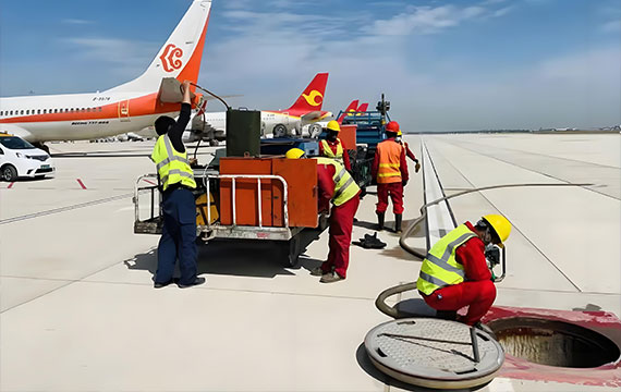
Typical Applications of Pipeline Plugs
Pipeline plugs serve distinct roles across different operating environments. Pipeline plugs are often used alongside hot tapping and line stopping services to enable live pipeline modifications.
Compressor and Pump Stations (High Cyclic Pressure)
Plugs isolate station piping for valve replacement or meter calibration without depressurizing the mainline. This application demands carbon fiber or mechanical plugs validated to 5+ million cycles due to daily pressure swings from compressor starts.
Offshore Pipelines
Subsea plugs are deployed via ROV (remotely operated vehicle) for emergency isolation or planned maintenance. Inflatable designs are preferred due to their ability to seal on irregular surfaces from marine growth or corrosion.
Urban Gas Distribution
Low-pressure (under 100 psi) plastic or cast iron mains are commonly isolated using inflatable plugs inserted through small-diameter access fittings. Speed of deployment and ease of retrieval are the primary drivers.
Emergency Leak Isolation
When a pipeline is ruptured or leaking, a plug can be inserted upstream of the damage to stop flow temporarily while permanent repairs are arranged. In these scenarios, pressure differential may be low, but deployment reliability is critical.
What Does the Installation Process Look Like for a High-Fatigue Pipeline Plug?
Proper installation of a high-fatigue pipeline plug requires abrasive blasting to a 50–75 micron anchor pattern, primer application within 4 hours of blasting, controlled curing below 60% relative humidity, and a full ultrasonic scan to verify bond integrity before pressurization. These procedures align with ASME PCC-2 composite repair standards и composite pipeline repair systems best practices.
Critical Steps for Surface Preparation
- Profile measurement – Anchor pattern must reach 50–75 microns (2–3 mils) using a replica tape.
- Salt contamination check – Bresle patch value below 20 mg/m²; higher levels inhibit primer adhesion.
- Primer application within 4 hours – After abrasive blasting, primer must be applied before oxidation returns.
- Curing under controlled humidity – Below 60% RH for epoxy primers; higher humidity causes amine blush.
Common Installation Mistakes to Avoid
- Using wire brushes instead of abrasive blasting (leaves smeared metal)
- Omitting the primer induction time (allowing chemical activation)
- Applying composite wrap before primer reaches tack-free state
- Ignoring pipe temperature vs. dew point (minimum 3°C spread)
Pipeline Plug vs. Line Stop: What’s the Difference?
Engineers frequently confuse these two pipeline isolation methods. The table below clarifies the distinction.
| Критерий | Трубопроводная заглушка | Line Stop |
|---|---|---|
| Mechanism | Internal sealing element expanded against pipe wall | External fitting with a temporary valve and plug inserted through a hot tap |
| Access required | Insertion through existing valve or small hot tap | Larger fitting (typically 2x–4x pipe diameter) |
| Pressure range | Low to medium (inflatable); high (mechanical) | Very high (up to 1,480 psi / 100 bar) |
| Bypass capability | Limited – most plugs block full bore | Often includes bypass to maintain flow |
| Permanent modification | None – plug removed after work | Fitting remains welded to pipe |
| Typical isolation duration | Hours to days | Days to weeks |
When to choose a pipeline plug: Short-term isolation, lower pressure, minimal permanent modification.
When to choose a line stop: Long-term isolation, full bore access required, ability to weld a large fitting is acceptable.
What Long-Term Field Data Supports Pipeline Plug Reliability?
Field data from a Gulf Coast natural gas transmission line operating since 2014 shows a carbon fiber pipeline plug retained 98% of original hoop stiffness after 1.4 million cycles (8 years of service), with zero adhesive disbonding detected via ultrasonic phased array. In comparison, a glass fiber plug on an adjacent line showed 15% disbonding at 2 years and was replaced at 3 years.
Case Example: Gulf Coast Gas Pipeline
- Line parameters: 24-inch diameter, 850 psi MAOP, 400–600 pressure cycles per day (compressor station proximity)
- Isolation plug system: High-toughness carbon fiber with silane-modified epoxy primer
- Installation date: March 2016
- Inspection intervals: Annually for 8 years
Results after 8 years of cyclic service (approx. 1.4 million cycles):
- No detectable adhesive disbonding (ultrasonic phased array)
- Composite hoop stiffness within 98% of original
- Zero gas leakage during annual spot checks
Why Choose Carbon Fiber Pipeline Plugs for Cyclic Pressure Isolation?
Carbon fiber (230 GPa) closely matches the elastic modulus of steel (200 GPa), distributing cyclic stress across the entire bonded adhesive area. Glass fiber (72 GPa) is significantly less stiff, creating shear stress concentration at the bond edges that leads to delamination under repeated pressure cycling. For any pipeline exceeding 200 pressure cycles per day, carbon fiber is the only reliable choice. This is a core principle of pipeline integrity management for dynamic service conditions.
Pipeline Isolation Methods: Where Plugs Fit
Plugs are one of several temporary isolation methods. Engineers should understand where plugs are optimal versus alternatives.
| Метод | Лучшее для | Limitation |
|---|---|---|
| Заглушка для трубопровода | Small-diameter access, short duration, lower pressure | Limited bypass capability |
| Line stop | Large diameter, long duration, full bore access | Requires large welded fitting |
| Freeze isolation | No hot tap or fitting allowed | Limited to small diameters, risk of ice plug failure |
| Double block and bleed | Permanent or semi-permanent isolation | High cost, requires existing valve station |
| Remote sealing robot | Unpiggable or unpiggable lines | Very high cost, limited availability |
Plugs are the optimal choice when existing valve access exists, isolation duration is under 72 hours, and permanent modification is undesirable.
Q&A: Common Engineer Concerns on Pipeline Plugs
What is a pipeline plug used for?
A pipeline plug is used to temporarily isolate a section of a pressurized pipeline, stopping flow to allow maintenance, repair, or modification without shutting down the entire system.
How does a pipeline plug work?
A pipeline plug works by expanding a sealing element—either mechanically or via inflation—against the pipe’s internal wall, creating a pressure-tight barrier that blocks flow downstream of the plug.
What is the difference between a pipeline plug and a line stop?
A pipeline plug is inserted internally through an existing valve or small hot tap, while a line stop uses a larger external fitting welded to the pipe. Line stops typically handle higher pressures and longer isolation durations.
What pressure can an inflatable pipeline plug handle?
For larger diameters (20–48 inches), most inflatable plugs are rated between 150 and 300 psi. Mechanical or composite-reinforced plugs can handle up to 1,480 psi (100 bar) or higher.
Can pipeline plugs handle cyclic pressure?
Yes, but only if designed specifically for cyclic service. Carbon fiber-reinforced systems with silane-modified epoxy primers have been validated to 10 million cycles under ASME B31.8. Standard glass fiber systems typically fail between 500,000 and 2 million cycles.
Request a Fatigue Life Assessment Based on Your Pipeline’s Pressure Cycle History
This guide combines laboratory validation, field case studies, and international standards to provide a complete engineering reference for pipeline isolation.
For engineering consultation, providers typically offer fatigue life assessments, carbon fiber vs. glass fiber comparisons, installation quality assurance, and full test data under NDA.
To request a site-specific assessment, provide the following information:
- Pipeline diameter (inches or mm)
- MAOP (psi or bar)
- Estimated daily pressure cycles
- Operating temperature range (°C or °F)
- Pipe material and wall thickness
Submit these parameters for a preliminary fatigue assessment. A pipeline integrity engineer will review your pressure history, calculate expected cycle counts, and recommend an appropriate carbon fiber or composite solution.