
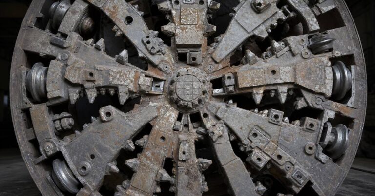
A mixed ground cutterhead (also called a faceplate, or a mixed-face head where both materials meet at the face) is a faceplate that carries soft-ground and hard-rock tooling at the same time. Two decisions define it: the tooling list and the opening ratio. Where a drive passes through alternating layers, or where softer material surrounds cobbles, boulders or rock, the cutterhead has to cut both materials at a single rotation speed and a single thrust setting – and that compromise is designed into the faceplate, not adjusted in the ground.
This guide explains what mixed ground and mixed face actually mean, the tooling families and what each one cuts, the opening ratio bands that separate soft, mixed and rock cutterheads, how gauge cutters set the overcut and the annular gap, how disc cutter spacing and thrust govern cutter life, how material is sized before it enters the faceplate, where wear protection belongs, and why tooling access decides whether a mixed-ground drive is recoverable or not.

Why Mixed Ground Is a Cutterhead Problem, Not a Machine Problem
Mixed ground is a cutterhead problem because a machine cannot change its cutting geometry underground. The drive speed and thrust that suit clay are wrong for a rock band, and the tooling that survives a rock band is not what cuts clay most efficiently. A mixed ground cutterhead is therefore a designed compromise with a defined operating window, and the quality of that design shows up as either a steady advance rate or a long series of stops. The fix is a faceplate and tooling list sized for the hardest interval the drive will meet, not for the average soil name.
- Mixed ground
- the alignment passes through more than one material – sand over rock, clay with cobble bands, weathered rock over fresh rock.
- Mixed face
- both materials are present at the cutterhead at the same moment, which is the harder case.
The Tooling Families and What Each One Cuts
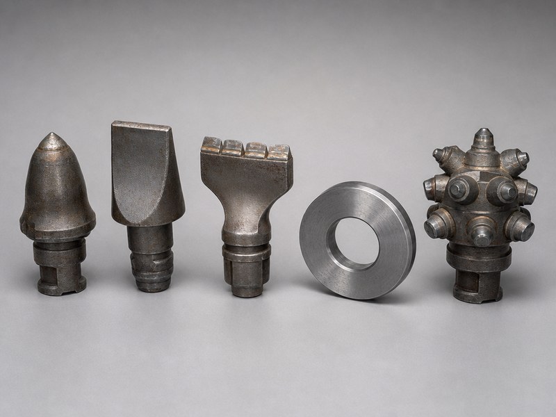
Cutting tools for microtunneling are grouped by the material they are designed to cut. A mixed ground cutterhead combines several families on one faceplate, and each family has a different wear behavior and a different replacement requirement.
| Tool family | What it cuts | Mounting and notes |
|---|---|---|
| Bullet and chisel teeth (carbide tipped) | Soft to medium soils; the standard choice for soft-ground and mixed-ground faces | Usually weld-on or bolt-on; replaceable bits range from simple plate to purpose-built mounts with carbide inserts |
| Scrapers and bucket scrapers | Soft ground and the softer fraction of a mixed face | Mounted on the faceplate spokes; used with disc cutters in rock cutterheads |
| Rippers and picks | Weak rock and fissured material | Sometimes used where rock is too strong for teeth but too weak to justify heavy disc tools |
| Disc cutters | Hard ground, rock bands, cobbles and boulders | Installed from the front or the rear of the faceplate; rear-loaded discs can be replaced from behind the cutting face |
| Gauge cutters | Outer edge of the bore | Set to overcut beyond the pipe outside diameter and to hold bore diameter at the edge of the face |
Published design guidance is consistent about the division of labor: soft-ground tooling typically includes cutter teeth, cutter bits and scrapers; disc cutters are used where hard ground or rock is expected; and mixed-ground cutterheads blend the two together. Cutting tools for microtunneling are also, in effect, consumables, so the specification has to include quantities and the change-out plan. On a mixed ground cutterhead, that change-out plan is what turns an unpredictable cost into a budget line.
Opening Ratio: The Single Most Important Faceplate Number
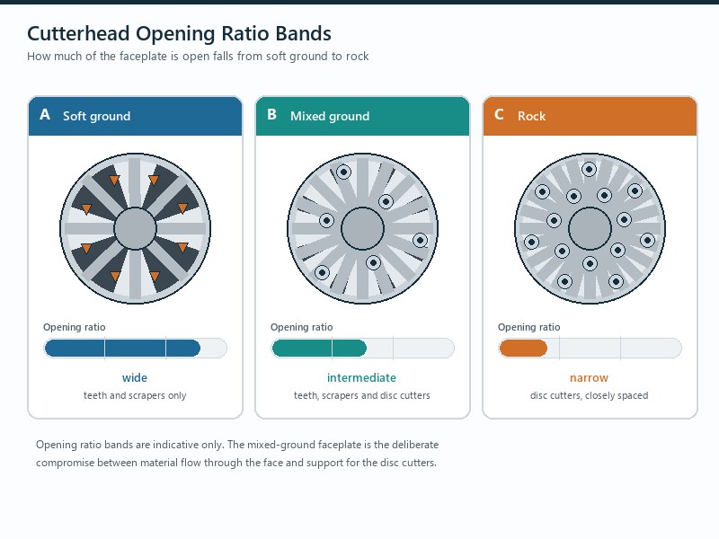
Opening ratio is the percentage of the faceplate that is open, and it controls how much excavated material can pass into the plenum. Throughout this guide, cutterhead and faceplate refer to the same component; face access is a separate feature of the machine. Published manufacturer design guidance sets out three bands, and the mixed-ground band is the compromise between cutting capacity and material flow.
| Cutterhead type | Typical opening | Почему |
|---|---|---|
| Soft ground | About 40% to 60% | Soft ground processes easily, so the largest openings are used to allow fast advance and unrestricted material consumption |
| Mixed ground | About 20% to 40% | Enough open area for soft and fractured material to pass, while keeping sufficient faceplate structure to support the disc tools cutting the hard fraction |
| Hard ground and rock | About 10% to 20% | Rock is processed by disc cutters into small fractured chips consumed around the disc spacing, so large openings are neither needed nor structurally desirable |
Too much open area in a mixed face lets soft material flow into the plenum faster than the machine can control the face, and reduces the faceplate stiffness that disc cutters rely on. Too little open area in a mixed face blocks the soft fraction, so the machine re-cuts material it has already excavated and torque climbs. In our construction reviews, a mixed-ground drive that repeatedly loses feed rate without a change in ground is usually a faceplate opening problem rather than a machine power problem.
Gauge Cutters, Overcut and the Annular Gap
Gauge cutters sit at the outer edge of the cutterhead, and their job is to hold the bore diameter slightly larger than the pipe outside diameter. In manufacturer practice, cutterhead outer gauge cutters overcut typically up to about 1 in (25 mm) in radius larger than the pipe outside diameter, to reduce friction on the pipe string as it is jacked through the ground.
The overcut left by the gauge cutters becomes the annular gap, and the annular gap is a design decision, not a by-product: choose it against the steering correction the alignment needs and the settlement the surface allows. Overcut is conventionally stated with reference to the radius, and typical industry ranges place it between about 5 mm and 50 mm, with the small end applying to bores of roughly 300 mm outside diameter and the large end to pipe jacking from about 3,000 mm outside diameter. Some specifications cap it more tightly: a published water-industry specification requires that the overcut of the tunneling shield not exceed 30 mm or 2% of the pipe outside diameter, whichever is smaller.
A generous annulus reduces skin friction and gives the machine room to steer back to line, while a tight one limits settlement at the surface but risks the pipe string binding. Under-sizing the annulus can stop a drive or crack pipes, especially in rock. If the cutterhead’s gauge cutters are worn, the effective overcut shrinks as the drive progresses, which is one reason gauge cutter condition is inspected rather than assumed.
Disc Cutters: Spacing, Thrust and Bearing Life
Disc cutters are rolling tools, and their performance depends on how hard they are pressed against the rock as much as on how many are fitted. Published guidance is direct about the relationship: closer disc spacing and higher thrust are required to process harder rock, and the quantity and size of the discs increases the cutterhead thrust capacity.
- Spacing. Closer spacing means more cutting passes per revolution and smaller chips, which suits stronger rock; wider spacing suits softer or more fractured material.
- Thrust. Disc life is a thrust-dependent variable. Thrusting too hard reduces disc bearing life, and a damaged disc bearing results in skidding and lost production.
- Load path. Thrust capacity has to be assessed at the cutterhead, not only at the machine. A faceplate with sufficient shaft thrust but insufficient disc coverage will not convert that thrust into rock cutting.
- Cut material size. Discs process material in front of the faceplate before it is consumed, which is why the openings between discs and the material sizing devices behind them work as a system.
Sequencing on a Mixed Face: Keeping Hard Inclusions from Rolling
On a mixed face, cutting order matters as much as geometry. In a face where soft material surrounds hard inclusions, the soft fraction has to be cut and flushed away without the hard inclusions migrating and wedging. That is a function of tooling layout, opening ratio and the material sizing measures described next. A mixed ground cutterhead holds a steady advance on a mixed face only when its tooling layout keeps hard inclusions from rolling free.
Material Sizing, Wear Protection and What Actually Wears Out
Material sizing, wear protection and inspection are three separate controls on one problem: keeping the faceplate able to cut for the whole drive length.
The material-sizing and intake arrangement sits behind the cutting tools and controls what passes into the plenum. Some cutterhead designs incorporate material grading screens to control the size of material allowed to pass through the cutterhead openings – commonly called grizzly bars – welded or bolted into the faceplate. Bolt-on grizzly bars can double as access doors to the face when tooling has to be changed, which is a useful example of one component serving both a process and an intervention purpose.
Wear, meanwhile, is governed by abrasiveness rather than by strength alone. Published guidance notes that abrasive material erodes the tooling and the base structure of the cutterhead, causing carbide inserts to fall out of cutter bits and rendering them useless for the remainder of the drive, and that abrasion can wear through a disc body until the bearing cavity is breached and the disc stops rotating. Manufacturers respond with hard-face weld or carbide-impregnated wear plates, and cutterheads and crushing cones are hard-faced to withstand wear. Abrasiveness is a separate property from strength, and the practical control is a defined wear limit measured at each intervention and compared with a scheduled tool-consumption allowance.
| Компонент | Wear mechanism | Protection and inspection point |
|---|---|---|
| Cutter bits and teeth | Abrasive ground erodes the body until carbide inserts fall out | Carbide-tipped inserts, hard-facing, and a defined wear limit measured at each intervention |
| Scrapers and buckets | Edge rounding and loss of cutting profile | Replaceable edges and periodic gauging against the original profile |
| Disc cutter body and bearings | Abrasion through the disc body, and bearing failure from over-thrusting | Wear plates and hard facing; seals and bearing condition checked against thrust records |
| Faceplate and structure | General abrasion of the base structure around tool mounts | Hard-face weld protection; inspection of mount integrity after the drive |
| Gauge cutters | Edge wear reduces effective overcut | Gauge measurement during intervention, compared with the specified overcut |
| Grizzly bars and openings | Deformation and build-up across the openings | Check for damaged bars; bolt-on versions inspected when used as access doors |
Tooling Access and Intervention: The Diameter Trap
Cutter wear is the normal cost of a mixed-ground drive. The question that decides whether the drive is recoverable is whether the tooling can be reached. Some cutterheads are designed to maintain tooling integrity throughout the entire drive length; others need the option to replace tooling underground, which requires a machine with face access.
For an owner or an EPC firm, intervention is a risk-allocation question: who carries the cost if the tooling does not last the drive. For a contractor or a bidder, it is a pricing question: whether tool consumption and any stoppage sit inside the rate or outside it.
For the designer writing the specification, the tooling list and the faceplate geometry are fixed before tender, not underground.
Three constraints govern face access. First, the machine needs an access door, and back-loaded tooling mounts let the crew work from behind the cutting face. Second, the ground has to make entry possible: in some conditions, ground stabilization or hyperbaric pressurization is required to perform underground maintenance of the cutterhead, which is why a compressed airlock package appears in microtunneling equipment lists for drives under groundwater. Third, published specification practice requires that cutterhead intervention or cutter change under free air or compressed air have a documented procedure submitted for approval about four weeks before work starts, where applicable.
This is the diameter trap: small bores have no man access, so intervention means recovering the machine or accepting the tooling condition to the end, while larger bores allow an access door whose use still depends on the ground and on the pressure regime. In our experience, the projects that suffered most from cutter wear were those where the intervention question was answered during the drive instead of at specification stage.
Итог: specify the tooling list, the opening ratio and the intervention method as one package. A mixed ground cutterhead is a compromise between flow and cutting; cutter wear is inevitable; and how the tools will be changed is a decision that has to be made before the machine is ordered, not after the advance rate drops.
Key Takeaways
- A mixed ground cutterhead blends soft-ground tooling with disc cutters, and is required where softer material surrounds cobbles or boulders, or where the drive crosses between soil and rock.
- Published opening bands are about 40% to 60% for soft ground, 20% to 40% for mixed ground and 10% to 20% for hard ground and rock.
- Gauge cutters set the overcut, typically up to about 25 mm (1 in) in radius beyond the pipe outside diameter, and some specifications cap overcut at 30 mm or 2% of pipe outside diameter, whichever is smaller.
- Closer disc spacing and higher thrust are needed for harder rock, but over-thrusting shortens disc bearing life and causes skidding and lost production.
- Abrasiveness, not hardness alone, drives cutter wear – which is why hard facing, carbide inserts and wear plates are specification items, not options.
- Face access decides whether cutter wear is a maintenance cost or a stoppage risk, and intervention procedures have to be documented before work starts.
Часто задаваемые вопросы
What is a mixed ground cutterhead?
A mixed ground cutterhead carries both soft-ground and hard-rock tooling on the same faceplate. Mixed-ground cutterheads blend cutter teeth, bits or scrapers with disc cutters, and they are required where softer material surrounds cobbles or boulders, or where a drive crosses between soil and rock.
What opening ratio should a mixed ground cutterhead have?
Published design guidance places mixed-ground cutterheads between about 20% and 40% opening. Soft-ground heads typically run 40% to 60% and hard-ground or rock heads 10% to 20%, so the mixed-ground band is the compromise that lets hard material be processed by disc cutters while softer material passes through larger scoop openings.
How many disc cutters does a microtunneling cutterhead need?
The number of disc cutters is set by the face area and the spacing the rock requires. Closer disc spacing and higher thrust are needed to process harder rock, and the quantity and size of the discs increase the cutterhead thrust capacity. Over-thrusting reduces disc bearing life, and a damaged disc bearing causes skidding and lost production.
Why does cutter wear matter more than cutter strength?
Abrasiveness, not hardness alone, decides how long tooling lasts. Abrasive material erodes tooling and the base structure, causes carbide inserts to fall out of cutter bits, and can wear through a disc body until the bearing cavity is breached and the cutter stops rotating.
What is face access, and when is it needed?
Face access is the ability to reach the cutterhead from inside the machine to replace tooling. It is needed where the tooling will not hold for the whole drive length, and it requires a machine with an access door and back-loaded tooling mounts. Some cutterheads are designed to maintain tooling integrity for the entire drive and do not need it.
What should the RFQ state about ground conditions and intervention?
A grading curve and a statement of whether tooling can be changed mid-drive. The RFQ should state the ground by interval, the strength and abrasiveness of any rock, the drive length, and the intervention method that will be used, so the cutterhead and the tooling list are designed for the actual drive rather than for a soil description.
How JSW Supports Cutterhead Selection and Intervention Planning
JSW is a pipeline engineering and construction company that executes trenchless crossings with its own crews and equipment. Our scope covers строительство методом микротуннелирования, бестраншейные технологии, HDD crossing services и услуги по прокладке трубопроводов, and our microtunneling capability covers ground from soft clay and sand through cobbles and mixed ground to hard rock up to about 80 MPa UCS.
We treat cutterhead specification as a risk-allocation exercise. Ground is specified by interval rather than by average, tooling lists carry expected consumption, and the intervention method – including the procedure and the pressure regime – is agreed before the machine is ordered, so cutter wear is a planned cost instead of an unplanned stoppage.
- Ground by interval, not by average: tooling and opening ratio chosen from the grading curve and the geology, including the mixed-face sections.
- Wear planned as consumable: expected tool consumption, wear limits and spares staged against drive length and abrasiveness.
- Intervention decided up front: the cutter change method and its procedure form part of the drive plan, not a contingency.
- Certified delivery: our trenchless work is delivered under ISO 9001:2015, ISO 14001:2015 and ISO 45001:2018 certified management systems.
Preparing a tender or a mixed-ground tooling package? Send the interval where the face turns mixed, your geotechnical log, drive length and expected advance rate for a free technical review. Our engineers respond with a scoped opening ratio, tooling list and intervention method, plus an indicative budget range.





































 English
  Arabic
  Russian
  Spanish
  French
  Vietnamese
  Polish
  Thai
Thai  Indonesian
  Turkish
  Portuguese