

HDD in rock is a tooling and technique problem before it is a geology problem. Can directional drilling work in rock? Yes – drilling through rock is routine when the tooling and rig are matched to the measured rock strength and abrasivity. The strength and abrasivity of the rock decide which pilot-hole method, bit type, reaming tool and drilling fluid will work, and how fast the bore can advance. This guide covers how rock is graded for drilling, how the main pilot-hole methods compare, how steering, reaming and fluid design change in rock, the torque and rig demand to expect, and the risks that most often decide whether a rock crossing succeeds.
What Makes HDD in Rock Different from Drilling in Soil?
Soil bores displace and compact ground; rock bores have to cut it. That one difference changes almost every downstream decision, from the bit on the end of the string to the viscosity of the drilling fluid and the number of reaming passes.
- Cutting method: soil is displaced and compacted; rock is cut, so the bit and the weight applied matter far more.
- Steering: tool-face control and build rates are harder to hold in strong rock, and every correction costs penetration.
- Tooling: a soil bore is often drilled with the rig’s rotary table alone; rock usually needs a mud motor or percussive tooling.
- Fluid and reaming: rock loses fluid through fissures and is opened in staged passes, while soil rarely forces either.
Rock Drillability: UCS Bands and Expected Penetration Behaviour
How Is Rock Drillability Described?
Rock drillability is usually described by two numbers: the unconfined compressive strength (UCS) of the intact rock, and its abrasivity. UCS is measured on an intact core sample by a uniaxial compression test. Abrasivity is most often reported as the Cerchar abrasivity index (CAI), which rises with quartz content and grain size and is the usual predictor of how quickly cutters and gauge wear out.
The familiar strength descriptors – very weak, weak, medium strong, strong, very strong – come from established rock classification practice, including the strength rating used in the Rock Mass Rating (RMR) system. UCS is the intact-rock strength; RMR is the rock mass rating that also accounts for structure and weathering, so a jointed or weathered mass can behave very differently from the core sample.
| UCS band (intact rock) | Strength descriptor | Expected penetration behaviour | Where it is typically met |
|---|---|---|---|
| Below 5 MPa | Extremely weak to very weak | Fast cutting at low torque; PDC (polycrystalline diamond compact) or rotary cutting is efficient and hole stability matters more than bit wear | Weathered rock, coal, chalk, very weak sandstone |
| 5 to 25 MPa | Weak | Steady penetration; PDC bits cut efficiently; hole cleaning and gauge control matter more than bit life | Weak sandstone, shale, soft limestone |
| 25 to 50 MPa | Medium strong | Moderate penetration; PDC preferred; torque and vibration rise and cutter wear becomes a cost item | Firm limestone, strong sandstone, mudstone |
| 50 to 100 MPa | Strong | Slower penetration as cutting shifts from shearing to grinding; higher weight and torque are required | Hard limestone, dolomite, strong sandstone |
| 100 to 250 MPa | Very strong | Low penetration rate; TCI (tungsten carbide insert) bits with staged passes; abrasive wear shortens bit life | Hard limestone, granite, basalt |
| Above 250 MPa | Exceptionally strong | Very low penetration; a down-the-hole hammer or specialty cutting; the penetration rate governs schedule and cost | Quartzite, very hard igneous rock |
How Do UCS Bands Map to Bit Families?
Selection guidance used across the trenchless industry maps the UCS bands above onto bit families.
- Rotary and PDC cutting: commonly recommended up to roughly 25,000 psi (about 172 MPa) compressive strength.
- Mill-tooth tricones: quoted to about 6,000 psi of unconfined compressive strength; TCI tricones: roughly 5,000 psi to over 50,000 psi of the same strength.
- Down-the-hole hammers: recommended for hard rock above about 30,000 psi.
These are selection bands rather than guarantees, because abrasivity and rock mass structure move the limits.
The unconfined compressive strength value comes from a small core sample, so it should be read alongside abrasivity and the rock mass structure. In our design reviews, the value that most often changes the method is not the average strength but the spread along the alignment, especially where a hard band sits inside otherwise drillable rock.
Pilot-Hole Methods in Rock: Mud Motor, Rotary Bit and Down-the-Hole Hammer
The pilot hole decides where the crossing runs, so the method has to deliver both cutting performance and steering. Three approaches cover most rock crossings.
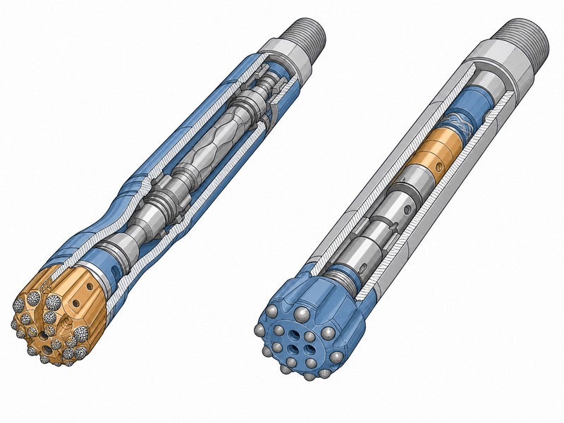
A mud motor drives the bit for directional control
In the mud motor method, the drilling fluid powers a downhole motor (also called a mud motor) that rotates the bit while the drill string is held and slowly worked. Because the bit turns independently of the string, a bent housing can be oriented to steer, which is what makes the method the default for directional work in medium and hard rock. The motor is normally run with a PDC bit in softer and medium rock, or a TCI bit where the rock is harder and more abrasive.
The motor itself needs a clean, lubricated fluid supply. Solids and poor lubrication shorten the motor’s working life, so hole cleaning and fluid conditioning are part of the method rather than an afterthought. In plain rotary drilling the string carries all the torque instead, the bit is turned by the rig, and there is no separate mud motor to orient.
On crossings we have supported, the motor is sized for the strongest and most abrasive band on the alignment rather than for the average core strength.
Rotary cutting suits softer ground
Plain rotary cutting, where the rig rotates the whole string, needs less downhole hardware and suits soft rock and soil. In hard, abrasive rock the string carries all the torque, which limits steering response, so the motor assembly is normally used instead.
A down-the-hole hammer handles the hardest rock
In very hard rock, a down-the-hole hammer (DTH) breaks rock by percussion rather than by pure rotation. It is credited with lifting penetration in hard formations and with less wear in abrasive ground, but it needs adequate air or fluid energy. Percussive tooling suits straighter bores with lower steering demand; where tight directional corrections are needed, a mud motor assembly is normally the better fit.
Reaming Strategy in Rock: Hole Opener, Rock Reamer and Staged Reaming
The pilot hole is smaller than the product pipe, so it has to be opened. Published good practice, including the NASTT HDD Good Practices Guidelines, puts the finished reamed hole at roughly 1.2 to 1.5 times the product pipe outside diameter. In rock that opening is usually built up in stages rather than in a single pass.
Hole opener or rock reamer?
A hole opener with mill-tooth or TCI cutters is the general-purpose tool for enlarging a bore. A rock reamer is the heavier, more aggressive tool used in hard or abrasive rock, often with a PDC or TCI cutting structure. Published guidance suggests that a hole opener is normally limited to removing about 4 inches of diameter per pass, while a heavier reamer can remove more in one pass in suitable ground. This is a published planning figure for one pass; the achievable step depends on rock strength, abrasivity and the reamer geometry, and must be confirmed for the actual crossing.
Staged reaming spreads the load: several passes step the diameter up toward the target, which keeps torque and cutter loads inside the rig’s and the tool’s limits. Backreaming – enlarging while pulling back toward the rig – is common in rock. The pass sequence is normally decided by the hardest interval on the alignment, not by the average; each rock class then carries its own pilot and reaming tooling and its own dominant risk.
| Rock class | Typical pilot tooling | Typical reaming tooling | Main risk |
|---|---|---|---|
| Soft, below 25 MPa | Rotary bit, motor optional | PDC reamer or light hole opener | Washout, hole collapse, over-cut |
| Medium, 25 to 50 MPa | Mud motor with a PDC bit | PDC or TCI reamer | Torque spikes, cutter wear, steering drift |
| Hard, 50 to 100 MPa | Mud motor with a TCI bit | TCI reamer in staged passes | Low penetration rate, bit wear, high thrust and torque |
| Very hard, above 100 MPa | Percussive tooling or a TCI motor assembly | TCI reamer, multiple staged passes | Very low penetration, severe wear, alignment deviation |
Drilling Fluid in Rock: Cuttings Transport, Viscosity and Motor Lubrication
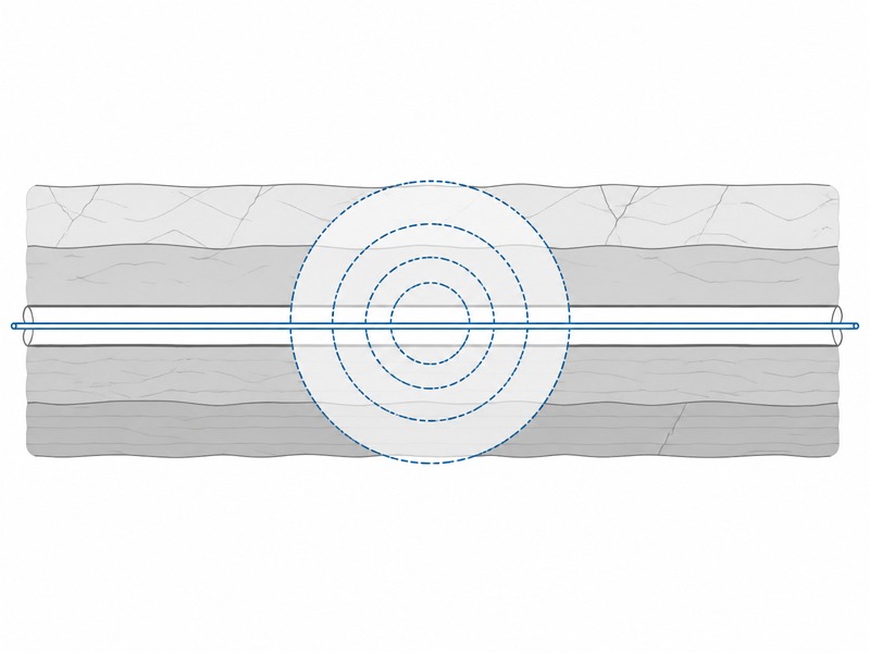
In a rock bore, the fluid has to do three jobs at once: carry cuttings out of the hole, keep the hole stable, and lubricate and cool the bit and any downhole motor. Soil rarely stresses all three together in the way that fractured rock does.
- Cuttings transport. Rock cuttings are heavier and more angular than soil cuttings, so annular velocity and fluid rheology have to be managed to lift them. Poor cuttings transport is a common cause of stuck pipe and rising torque.
- Viscosity and rheology. A fluid with the right viscosity suspends cuttings when circulation stops; in rock the balance is set by test, not assumed from a soil-based recipe.
- Motor lubrication and cooling. Where the motor is used, the fluid is also the power and lubrication medium, so solids control on the surface directly affects tool life.
- Loss control. Because rock loses fluid through fissures, the fluid programme needs a planned response for loss zones, an inadvertent-return check and a defined monitoring routine.
We have seen fluid programmes that were adequate in soil fail within a short distance in fractured rock, which is why the fluid plan belongs in the design phase and not only on the rig site. The geotechnical profile should identify the likely loss zones in advance.
Torque and Rig Demand in Rock: When Casing Is Needed
What Torque and Thrust Does Rock Demand?
Rock raises the demands on the rig: more torque, more thrust, and a larger fluid pump. A staged reaming plan keeps those demands inside the selected rig class, and the pilot method follows the same limit.
Rig classes follow DCA practice, where mini, midi and maxi machines are classified by capability and published machinery ranges span roughly 3.6 t to 617 t of pullback force, with maxi rigs often described as greater than 100 t and midi rigs at roughly 15 to 40 t pullback and 15 to 30 kN.m of torque. Class boundaries differ between organisations, so the capacity figure for the actual crossing – not the label – should drive selection.
Rig class selection for a rock crossing follows the same class logic as any other HDD crossing; the rock raises the demand, but it does not change how the classes are defined.
When Is Casing Needed Through Rock?
Casing through rock is needed where the ground is fractured, running or karstic, or where the crossing authority requires it. A casing or casing sleeve can protect the bore and the product pipe there, and some authorities require it. In our design reviews, the casing decision through rock is made once the reamed hole size and the fractured intervals are known, not on site; the casing size, wall thickness and annular clearance all follow from the reamed hole and the product pipe data.
What Are the Main Risks of HDD in Rock?
The main risks of HDD in rock are not the same as those in soil, and most of them trace back to the geological detail between the boreholes rather than to the drilling method itself.
- Fracture and fissure fluid loss. Fractures, bedding planes and solution features can take fluid faster than the replacement rate.
- Karst. Voids and solution channels can swallow the bit or divert the bore off line.
- Steep rock-head transitions. Where soil meets rock abruptly, steering can break down and cover can be lost.
- Tool wear. Abrasive rock wears cutters, gauge and stabilisers faster than planned.
- Low penetration rate. In very strong or abrasive rock, a low penetration rate can stretch the schedule.
| Risk | Trigger | Design response |
|---|---|---|
| Fracture and fissure fluid loss | Open fractures and bedding planes that take fluid faster than it can be replaced | Identify the loss zones early and set the fluid programme before drilling |
| Karst | Voids and solution channels along the alignment | Confirm cover and keep the bit supported along the alignment |
| Steep rock-head transition | An abrupt change from soil to rock along the bore | Manage build and steering so cover is not lost over a short distance |
| Tool wear | Abrasive rock wearing cutters, gauge and stabilisers | Budget the tooling and the pass plan for wear |
| Low penetration rate | Very strong or very abrasive rock against the rig’s torque limit | Plan extra passes and price the schedule risk explicitly |
Our field teams record that the most expensive rock problems are rarely predicted by a single borehole: they appear where the ground changes between the investigation points. That is why the geotechnical profile along the alignment, not one log, drives the risk assessment.
Часто задаваемые вопросы
What is HDD in rock?
HDD in rock is horizontal directional drilling through rock rather than soil, which needs a cutting bit and usually a downhole motor or a percussion hammer. Because rock is cut rather than displaced, the tooling, steering, reaming and fluid decisions all change.
Can horizontal directional drilling drill through solid rock?
Yes, HDD is routinely used in rock, including very hard rock, provided the right tooling and rig are selected. The method is chosen from the rock strength and abrasivity, and hard rock is normally drilled with a downhole motor and a TCI or PDC bit, or with a percussion hammer.
Which bit type suits hard rock in HDD?
The bit follows the measured rock strength and abrasivity. PDC bits cut efficiently in soft to medium rock, TCI bits cover a wide strength range and tolerate more abrasive ground, and percussive tooling is used in the hardest rock.
How is the reamed hole sized in rock?
The finished reamed hole is typically 1.2 to 1.5 times the product pipe outside diameter, built up in staged passes in rock. A reaming tool removes a limited diameter per pass, and the sequence is set by the hardest interval on the alignment.
Why does drilling fluid get lost in rock?
Drilling fluid is lost in rock because open fractures, bedding planes and karst features take fluid faster than the bore can hold it. Loss is managed by identifying the loss zones from the geotechnical data and setting the fluid programme and response before drilling starts.
Is HDD in rock slower than in soil?
Usually yes, because rock is cut rather than displaced, and the drilling rate falls as strength and abrasivity rise. The difference is greatest in very strong or very abrasive rock, where extra reaming passes and more tool wear add time and cost.
Key Takeaways
- HDD in rock is a tooling and technique decision first; the rock strength and abrasivity set the method, the bit and the reaming plan.
- Rock strength, usually reported as unconfined compressive strength, and abrasivity are the two numbers that most often drive tool selection.
- The method follows the rock: a mud motor for directional work in medium and hard rock, plain rotary cutting in softer ground, percussive tooling in the hardest rock, then staged reaming to a hole typically 1.2 to 1.5 times the product pipe outside diameter.
- Cuttings transport, fluid loss control and motor lubrication are design inputs, not field improvisation.
- Fracture and fissure fluid loss, karst, steep rock-head transitions, tool wear and slow drilling are the risks to price.
How JSW Supports HDD in Rock Crossings
JSW is a pipeline engineering and construction company that drills rock and mixed-face crossings with its own crews and equipment. Our scope covers HDD crossing services и бестраншейные технологии for bores that have to cut hard ground. It extends to automatic pipeline welding, pipeline cold bending и услуги по прокладке трубопроводов, so the pipe string that follows a rock bore is fabricated and placed by the same crews.
Because the bore profile, tooling choice and reaming plan sit under one contract, they are matched to the rig and to the rock actually logged rather than to a generic rate. Rock-related risks are priced separately with their trigger conditions, and the design basis, fluid programme and installation records are archived for later review.
- Комплексная доставка: tooling selection, bore profile, reaming plan and pullback sit in one scope, removing the interface between designer and driller.
- Auditable engineering: geotechnical interpretation, tooling selection and fluid records are documented for review.
- Ценообразование с учетом риска: rock-specific risks such as fluid loss and tool wear are listed with trigger conditions rather than wrapped into a single price.
- Crossing experience: rock, mixed-face and transition crossings are planned alongside restoration and permitting.
Planning a crossing through rock? Send your bore profile, rock core logs with strength and abrasivity results, the rock-head profile, the product pipe data and the site constraints for a free technical review. Our engineers respond with a tooling and method recommendation, the rock-related risks we see, and a budget range.





































 English
  Arabic
  Russian
  Spanish
  French
  Vietnamese
  Polish
  Thai
Thai  Indonesian
  Turkish
  Portuguese