
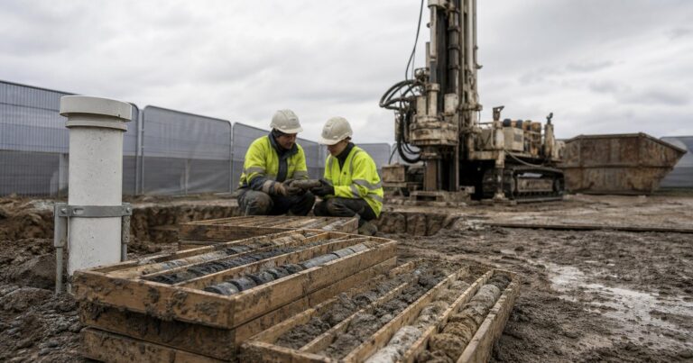
A microtunneling geotechnical investigation is the desk study and ground investigation package that decides whether a drive is feasible and what machine, face support and jacking force it needs. Its three outputs are a borehole layout, a parameter list and a baseline deliverable set, and its placement rule is fixed: boreholes are sunk beside the alignment and the shaft positions, never on the tunnel line, and they extend to the tunnel horizon and below the invert. This guide sets out the borehole placement rules, the field methods that are used, the parameters to test by ground type, the rock and mixed-ground data that is often missed, and the baseline deliverables an owner should demand. Every value here is an input to project-specific design, not a substitute for it.
Why Does the Desk Study Come Before Any Borehole?
The desk study decides where to bore and what to test, so it comes before any intrusive work rather than alongside it. It turns a general understanding of the route into a targeted scope and stops the investigation from becoming a scatter of holes that misses the ground that matters.
A useful desk study draws together published geological maps and memoirs, previous ground investigations in the area, mining and quarry records, historical land use and contamination records, and the utility records for the corridor. It identifies the strata likely to be present, the depth of the water table, the presence of fill, the likelihood of boulders or a rock head, and the locations where the ground changes. Each of those factors then sets a requirement for the microtunneling geotechnical investigation that follows, whether that is a deeper borehole, a pumping test or an additional piezometer.
In our design reviews, the most common cause of a late scope change is a route that moved after the investigation was planned but before it was carried out. The published rule is straightforward and worth repeating: re-review the scope if the route changes, because a scope that suited the old alignment rarely suits the new one.
The desk study also sets the questions the intrusive work has to answer. If the route runs through old industrial land, the investigation needs to test for contaminated ground and gas as well as for strength; if it crosses a river or a tidal reach, it needs to characterise the seasonal variation in groundwater.
Where Should Boreholes Be Placed for Microtunneling?
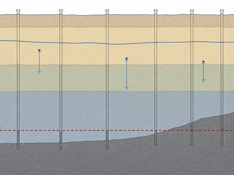
If the question is where a microtunneling geotechnical investigation should place its boreholes along a drive of a few hundred metres, the placement rule is fixed: the Pipe Jacking Association sets it, and boreholes must not be sunk on the line of the tunnel. They are placed adjacent to the shaft locations, and additional holes are added at geological changes or wherever uncertainty remains, so that the drive is characterised rather than just the launch end.
- Never on the tunnel line. A borehole left in the path of the machine is an obstruction, so holes are offset and placed beside the alignment.
- Adjacent to the shaft locations. The shafts are where deep excavations, base stability and groundwater control are decided, so they need the densest information.
- Always to the tunnel horizon and below the invert. The hole must go far enough below the invert to identify strata changes that could affect construction, including a rising rock head that could push the machine up.
- Add holes where geology changes or uncertainty remains. A single hole per shaft is rarely enough; the profile between holes has to be inferred, and extra holes reduce that guesswork.
- Install piezometers. Groundwater level and its response are monitored with piezometers installed in the investigation holes and left in place; a piezometer left beside a shaft records the level that the shaft design has to allow for, through the seasons and through the works.
- Hand over in AGS format (a structured digital format for geotechnical and geoenvironmental data). The data is delivered in a structured format so it can be loaded directly into the designer’s software.
- Re-review the scope if the route changes. The placement rules follow the alignment, so a change of route triggers a change of scope.

Which Field Methods Are Used in a Microtunneling Geotechnical Investigation?
If the question is which field methods a microtunneling geotechnical investigation should combine to characterise a drive, the answer is boreholes with in-situ tests, pits and geophysics, because no single method gives both the samples and the coverage a drive needs. The method mix is chosen to answer specific questions about strength, permeability, abrasivity and stratigraphy.
| Метод | What it gives | When it is used |
|---|---|---|
| Rotary boreholes | Continuous cores and samples for logging and laboratory testing | The main method for rock and for most soils |
| Percussive boreholes | Penetration resistance records and disturbed samples | Coarse or variable ground where quick coverage is needed |
| Cone penetration tests | Continuous in-situ strength and a detailed stratigraphic profile | Soft to firm soils, fill and alluvial ground |
| Trial pits | Direct inspection of shallow ground and buried services | Shallow cover and utility verification |
| Geophysics | Continuity of strata between boreholes | Extending coverage where holes are far apart |
| Pumping tests and pump-down tests | Permeability and groundwater response under drawdown | Where dewatering or face support depends on inflow |
The pumping test is the method that most often changes a design, because it measures how the ground actually yields water rather than how a small sample suggests it might.
Geophysics is used to join the boreholes together: it indicates where the strata change between holes and where a rock head rises, and it then targets additional boreholes rather than answering the design questions on its own. Trial pits follow the same discipline: they are useful for shallow ground and for confirming a service, and their reach stops well above the tunnel horizon.
Which Parameters Must Be Tested, and What Does Each Decide?
The parameter list is long because each parameter answers a different design question, and the list differs by ground type. The Pipe Jacking Association sets out the parameters to consider by soil type, and the parameters group by what they decide.
| Ground type | Parameters to test | What they decide |
|---|---|---|
| Non-cohesive soils | Unit weight and moisture content, angle of friction, particle size distribution, abrasivity, SPT (standard penetration test), permeability and the nature of groundwater flows including seasonal and tidal changes | Jacking force, cutterhead and tool wear, face support method and dewatering |
| Cohesive soils | Unit weight and moisture content, cohesion, plasticity indices, mineral types and proportions | Jacking force, face support and the risk of clay clogging the cutterhead |
| Mixed ground and fill | Frequency and properties of boulders, cobbles or flints, presence of gases, toxic or hazardous constituents | Cutterhead selection, ground conditioning, disposal and working safety |
| Rock | Rock compressive strength, RQD, core logging with total core recovery (TCR), solid core recovery (SCR) and fracture index (FI), tensile strength, specific energy, slake durability | Excavatability, cutter wear, machine selection and rate of advance |
Abrasivity is easy to overlook in a tender and expensive to discover at the face, because it drives cutter material, wear allowance and the number of cutter changes a drive will need. In our design reviews, a microtunneling geotechnical investigation becomes a design basis only when it reports abrasivity, the size and frequency of boulders, and permeability: those three are the parameters that most often change the machine selection.
The parameter list has to cover the groundwater as well as the soil, because permeability and groundwater flows decide the face support method and the dewatering design. Toxic or hazardous constituents decide how excavated material can be handled and disposed of. A single piezometer reading taken on one day is a snapshot; a piezometer watched through the seasons is what shows whether the design should be built around a winter high water table. In our design reviews, a parameter table that lists strength and grading but omits permeability and contamination is usually the one that returns to site for a second investigation.
What Extra Data Does Rock and Mixed Ground Need?
Rock and mixed ground need core-based data, because the machine has to cut or break the material rather than simply displace it. The core log and its indices carry more of the design than a single strength number.
- Rock compressive strength. Sets the cutting energy and the cutter type the machine needs.
- RQD and core logging. The rock quality designation and the core logging indices – total core recovery, solid core recovery and the fracture index – describe how broken the rock is, which affects both excavatability and stability.
- Tensile strength and specific energy. Specific energy is a practical measure of how hard the rock is to cut, and it feeds machine selection and advance rate expectations.
- Slake durability. Describes how the material breaks down when exposed to water, which matters for handling and disposal as well as for the face.
- Boulders, cobbles and flints. Their frequency and properties decide whether the machine can pass them and how much the cutterhead is at risk.
Rock wedging is the reason this data matters to line and grade as well as to production: a machine pushed off line by a rock head or a boulder can be difficult to bring back without an abrupt correction, which is itself a risk. We have seen drives where the logged core and the RQD told the story clearly after the event and could have told it before, which is why we treat the core log as a primary design input rather than a supporting document. Our field teams log the core beside the penetration record, so a mixed-ground proportion is read from two sources before it is trusted from one.
Mixed ground is often the hardest to characterise, because the machine meets rock and soil in the same face and the proportion between them changes along the drive. Core recovery in mixed ground can be poor, so the log has to be read together with the penetration records and the geophysics rather than trusted on its own.
What Should the Baseline Deliverables Include?
The investigation should hand over a defined set of deliverables, and the three parties who use them read the same data differently: a municipal water or sewer owner checks that the ground risk is priced, an EPC bidder checks that the parameters support a machine selection, and a third-party design consultant checks that the profile extends along the whole alignment. That set is more than a folder of logs. A usable deliverable set is one a design team can act on: the logs, the characterisation profile, the parameter ranges and the risk register are read as one package rather than as separate documents.
In UK practice, the logs are written to a recognised logging standard such as BS 5930, and the AGS format carries the same data into the designer’s software.
| Deliverable | What it contains | Why it matters |
|---|---|---|
| Borehole logs and core records | Descriptions, depths, samples, tests and photographs | The primary evidence behind every design assumption |
| Geotechnical characterisation profile | Strata interpreted along the whole alignment | Shows the ground the machine will actually meet, not just at the holes |
| Design parameters with ranges | Strength, stiffness, permeability and abrasivity values | Lets the designer test sensitivity instead of relying on single values |
| Risk register | Ground-related hazards and their triggers | Turns investigation findings into priced, manageable risks |
| Settlement prediction | Predicted surface movement along the route | Sets monitoring and mitigation before construction starts |
| Dilapidation baseline | Recorded condition of assets near the works | Separates pre-existing defects from construction effects |
The geotechnical characterisation profile is the deliverable that most often distinguishes a good investigation from an adequate one. A set of logs answers questions about the holes; a profile answers questions about the drive, and it is the profile that a microtunneling geotechnical investigation should be judged on.
The parameter tabulation should also carry the levels recorded by each piezometer and the results of each pumping test alongside the soil and rock values.
How Is Utility Verification Handled Before Design?
Utilities have to be verified to a stated quality level before design, because an unrecorded service is a hard obstruction rather than a design variable. Verification goes beyond the records: the position and depth of the services that matter have to be confirmed in the ground.
Verification combines the desk study of utility records with trial pits, vacuum excavation or alignment holes at a defined density. Caltrans trenchless guidelines require alignment holes at a maximum spacing of 200 ft, which is about 61 m, and that figure is a useful marker for the density of utility verification along an alignment where cover is shallow and the corridor is congested. The result feeds both the alignment and the risk register, and it is usually the trigger for a scope change if a service is found where none was recorded.
The settlement prediction built on this baseline is treated in our settlement control guide, the permeability and groundwater record in our microtunneling groundwater control guide, and the shaft positions that set borehole locations in our shaft sizing guide.
Часто задаваемые вопросы
Where should boreholes be placed for a microtunneling drive?
Boreholes must not be sunk on the line of the tunnel. They are placed adjacent to the shaft locations and in a way that characterises the ground along the alignment, with additional holes wherever the geology changes or uncertainty remains, so that the whole drive is covered rather than just the launch.
How deep should a microtunneling borehole go?
A borehole must always extend to the tunnel horizon and far enough below the invert to identify strata changes that could affect construction, including a rising rock head that a machine could be pushed onto. Providing cover below the invert is what protects the drive against an unexpectedly shallow rock surface.
What is AGS format and why does it matter?
AGS is a structured digital format for geotechnical and geoenvironmental data. Requiring the investigation to be handed over in AGS format means the logs, the tests and the monitoring data can be loaded into the designer’s software and re-used, rather than being re-keyed from paper reports.
What is abrasivity and why does it matter in microtunneling?
Abrasivity describes how strongly the ground wears the cutterhead and tools. It is a design input for cutter material, wear allowance and the number of cutter changes expected, and it is one of the parameters that must be tested when selecting a microtunneling machine for a drive.
Why install piezometers for a microtunneling drive?
Piezometers record groundwater levels and how they respond to the drive. They are used to identify seasonal or tidal variation, to check drawdown caused by dewatering, and to confirm the groundwater pressures that face support and shaft seals have to resist.
What should a geotechnical investigation deliverable include?
The baseline should include the borehole logs, a geotechnical characterisation profile along the alignment, design parameters with ranges, a risk register, a settlement prediction and a dilapidation baseline. Utility verification to a stated quality level is also part of the package before design is fixed.
Key Takeaways
- The desk study comes first and sets the scope of the microtunneling geotechnical investigation, including where to bore and what to test.
- Boreholes must not be sunk on the tunnel line; place them beside the shaft locations and always extend them to the tunnel horizon and below the invert.
- Field methods span rotary and percussive boreholes, cone penetration tests, trial pits, geophysics and pumping tests, because each answers a different question.
- Parameters must be tested by ground type, and abrasivity, boulders and permeability are the ones that most often change the machine selection.
- The baseline deliverables are logs, a characterisation profile, design parameters with ranges, a risk register, a settlement prediction and a dilapidation baseline, preferably in AGS format.
- If one output has to be prioritised, it is the characterisation profile along the alignment: a deliverable set is a design basis only once the profile draws the tunnel horizon and the invert, the parameters carry ranges, and the log has been checked against the penetration record.
- Every parameter and range on this page is an input to project-specific design and must be confirmed by a competent engineer for the actual drive.
How JSW Supports Microtunneling Geotechnical Investigation
JSW — это компания, специализирующаяся на проектировании и строительстве трубопроводов, которая осуществляет бестраншейную прокладку трубопроводов собственными силами и с использованием собственного оборудования. В сферу нашей деятельности входят строительство методом микротуннелирования, where the ground model from a microtunneling geotechnical investigation is tested against the drive, together with the wider бестраншейные технологии portfolio where a crossing needs a different method. Where the ground suits a different crossing method we provide HDD crossing services, and we deliver услуги по прокладке трубопроводов и pipeline inspection service so investigation, design, the drive and the as-built records stay in one line of responsibility.
Because the design basis and the construction team sit together, the ground model from the microtunneling geotechnical investigation is tested against the equipment and crews that will execute the drive, and ground risks are priced separately with their triggering conditions stated. Investigation data, parameter ranges and the risk register are archived so the design can be audited during construction and afterwards.
- Комплексная доставка: investigation review, ground model, machine selection and drive execution under one scope, removing the handover between designer and constructor.
- Auditable engineering: the parameters, their sources and the assumptions built on them are recorded, so a reviewer can trace each design value to the borehole and test behind it.
- Ценообразование с учетом риска: boulders, mixed face, gas and groundwater risks are identified and priced against defined triggers rather than bundled into one figure.
- Investigation-guided delivery: additional boreholes, piezometers and utility verification are built into the programme where the ground or the corridor demands them.
Planning a microtunneling drive on an uncertain ground model? Send the alignment, the available borehole logs and the utility records for the corridor. Our engineers return a scoped review of what still has to be bored, tested and baselined, and a budget range for closing the gaps, with the parameters we would expect to govern the machine selection and the profile checks we would look for first.





































 English
  Arabic
  Russian
  Spanish
  French
  Vietnamese
  Polish
  Thai
Thai  Indonesian
  Turkish
  Portuguese