
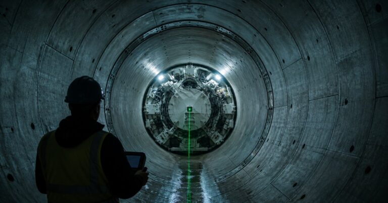
Microtunneling grade control is the closed loop of measurement, reporting and steering that keeps the machine on its design line (horizontal position in plan) and its design grade (the designed fall, expressed as a percentage or an elevation) as it advances. Accuracy as good as ±10 mm has been reported for microtunneling in one published reference, and it is achievable in favourable conditions – a straight drive, shallow cover and homogeneous ground – but it degrades with diameter, depth, mixed faces and obstructions. The ±10 mm figure comes from closing the control loop often and correcting gently, with a laser target system to about 200 m and guidance reported at intervals no greater than 2 seconds in the published envelope. If the question is how close to line and grade a drive of a given length can actually be held, the answer starts from the ground and the geometry and is then confirmed by the guidance record, rather than from the tolerance clause alone. That band holds only while the geometry and the ground stay favourable, so the loop and the ground have to be judged together.
What Is Microtunneling Grade Control and What Does It Govern?
Grade control governs two things at once: where the machine is, and where the pipe behind it will end up. The two are not identical, because the pipe follows the bored hole rather than the machine, and the hole is larger than the pipe. Control is therefore always a matter of keeping a predicted position inside an acceptable band, and the band is set by how far the pipe can sit from the reference and still do its job when it is commissioned.
The reference alignment is a horizontal line and a design grade, with tolerances attached for each. The achieved alignment is what the guidance system reports and what the survey confirms. The gap between them is what the steering system is trying to close.
- Reference input – the design line, grade and tolerance band.
- Measurement – machine position, roll, inclination and articulation attitude.
- Comparison – deviation from the reference, in line and grade.
- Correction – a controlled steering adjustment that respects the joint deflection limit.
The tolerance itself comes from the pipe’s duty, not the method. A gravity sewer may need ±50 mm horizontally and ±30 mm vertically with ±0.25% grade, while a casing can accept ±500 mm and ±100 mm. Grade control has to be tight enough for the strictest of those duties that the drive must satisfy.
Reference Alignment vs Achieved Alignment: The Control Loop
The control loop runs continuously from launch to reception. The guidance system reports the machine position against the reference, the operator or the automatic system compares that to the design, and a steering correction is applied. The loop then repeats on the next report.
Speed of reporting matters as much as the accuracy of any single reading. A published utility specification requires guidance to report, at intervals no greater than 2 seconds, the distance from the launch shaft, the roll, the inclination and the attitude across the articulated section of the machine. At a normal advance rate that is far finer than the pipe length, so deviation is caught while it is still small enough to correct gently.
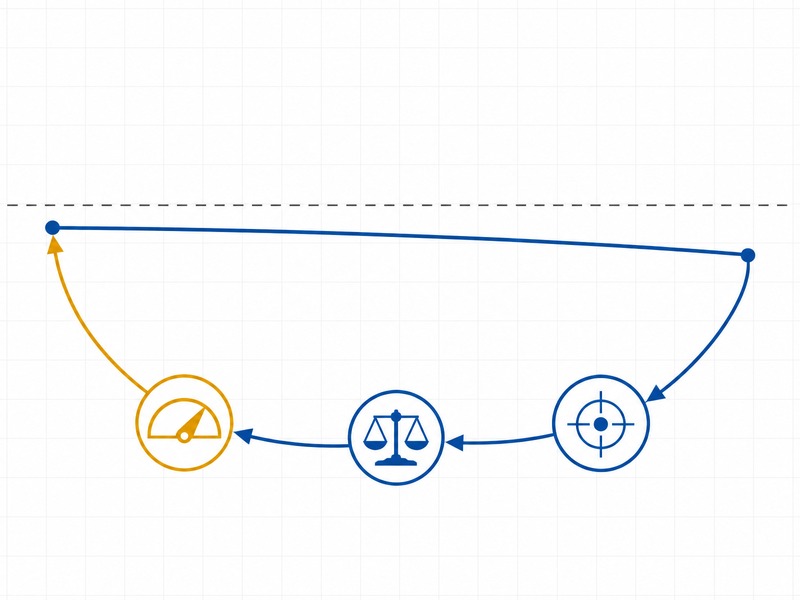
In our design reviews we treat the reporting interval and the correction limit as specification items rather than operator preferences. A machine with a capable guidance system but a slow reporting interval still wanders, because each correction is applied against a position that is already out of date; the loop only holds the line when both the interval and the correction limit are fixed in the design.
Which Guidance System Fits the Drive: Laser, Gyro or Total Station?
The choice of guidance system is the technology half of microtunneling grade control. Each option has an envelope defined by drive length, tunnel diameter and curvature, and the envelope should drive the selection rather than convenience. Read the table as a switching rule rather than a ranking: the laser target system holds while the beam line of sight is available to about 200 m, and a gyro guidance system takes over beyond that distance and wherever the alignment curves away from the launch.
| Guidance option | Envelope | Примечания |
|---|---|---|
| Laser target system | To about 200 m; minimum tunnel diameter about 900 mm (Unitywater Pr9787 envelope) | Projects a beam to a target on the machine; reports the target at the rear of the machine to about ±1 in. (25 mm), degrading as the drive lengthens (Tunnel Business Magazine / North American Microtunneling Association specifying article) |
| Gyro guidance system | Drives over 200 m and curves | Used where the laser line of sight cannot be held; gyro audit campaigns between 120–170 m from drive start and 100 m from the finish on man-entry drives (Unitywater Pr9787) |
| Motorized total station with laser target | Resolves horizontal and vertical position, pitch and roll | For curves, used with a relay or with the laser physically repositioned to keep line of sight |
| Guidance reporting interval | No greater than 2 seconds | Distance from the launch shaft, roll, inclination and articulation attitude |
The laser option is the default for shorter, straighter drives, and it is simple and reliable while the beam can be seen. Its weakness is that the beam spreads and refracts, so the reported accuracy decreases as the drive lengthens, and temperature variation inside the pipe string makes the beam wander. A gyro guidance system does not depend on line of sight, which is why it takes over on long drives and curves, but it is used with periodic audit campaigns to keep its drift in check.
The machine itself is also part of the envelope. Microtunneling machines are remotely controlled and generally non man-entry, and the small-diameter machine class is typically quoted as 150–1000 mm, which is one reason a laser target system with a minimum tunnel diameter of about 900 mm does not suit every drive.
Selection should be made on the drive, not on habit. A short, straight sewer drive with a visible beam is well served by the laser option; a long drive, a curved alignment or a crowded shaft where the line of sight is broken calls for a gyro guidance system with audit campaigns. Where both are used on one contract, the changeover point should be stated in the method statement so that the survey basis is not lost between systems. On the drives we have supported, the changeover from laser to gyro is the point where the survey basis is most often lost, which is why we write it into the method statement before launch.
How ±10 mm Is Achieved on a Favourable Drive
The 10 mm figure describes how closely the guidance system can report the machine position, not where the pipe finally comes to rest inside the bored hole. The figure is achievable when the drive gives the control loop an easy task: a straight alignment, modest diameter, shallow cover and homogeneous ground. Under those conditions the guidance system is accurate, the machine responds predictably, and corrections can be small and infrequent.
Several conditions have to hold together for the figure to be credible:
- Uniform ground – the cutterhead meets the same resistance across its full face, so the machine does not get pushed sideways.
- Shallow, stable cover – there is less ground load and less opportunity for the trough to form above the pipe.
- Short, straight drive – the laser beam stays bright and the guidance reporting error stays small.
- Disciplined correction – the operator keeps every adjustment inside the permitted joint deflection.
Even then, the ±10 mm reported figure may be coarser where large diameter pipes are involved, because a heavier machine and a larger overcut give the pipe more room to move inside the bored hole. The figure describes a best case in favourable ground, and a specific drive should be assessed against its own geometry and ground before that band is treated as achievable.
Why Accuracy Degrades: Diameter, Depth, Mixed Face and Geology
When the ground stops being uniform, grade control has to fight for every millimeter. The deviation mechanisms are well documented, and most of them act on the machine by giving it unequal resistance rather than by defeating the guidance system. The accuracy a drive can hold is decided by the ground and the geometry rather than by the guidance system alone. For a municipal sewer owner comparing bids, an EPC bidder pricing a long drive, or a third-party design consultant checking a specification, the practical question is whether a specific drive, such as a 400 m drive, can be accepted at a given tolerance, and the answer starts from the ground and the geometry rather than from the clause.
| Фактор | Why accuracy falls |
|---|---|
| Large diameter | A heavier machine and a larger overcut leave more room for the pipe to sit off line inside the bored hole |
| Глубина | A longer guidance path and more opportunity for refraction and beam diffusion in the pipe string |
| Mixed face | Different resistance across the cutterhead pushes the machine off line and grade |
| Mixed reach | Ground conditions changing along the drive alter the response to the same steering input |
| Weak soils | Insufficient bearing capacity lets the machine sink or rise under its own weight |
| Soil over bedrock | The rock head pushes the machine upward as it crosses onto the harder material |
| Boulders and obstructions | Hard contacts deflect the machine and can cause pipe wedging through rock cuttings |
Two of these deserve attention in design. A mixed face is the classic case where the machine drifts because one side of the cutterhead is in stiff material and the other in soft: no amount of correction discipline can match a resistance the operator cannot predict. Soil over bedrock produces the opposite problem, a rock head that steadily lifts the machine. Both should be identified in the geotechnical investigation and allowed for in the tolerance the design promises.
Depth cuts both ways. A deeper drive needs a longer guidance run, so beam diffusion and refraction have more distance over which to act, and the machine is harder to inspect or realign. Against that, deeper ground is often stiffer and more uniform than the surface layers, which can make the machine respond more predictably. The net effect is site-specific and should be judged from the investigation rather than assumed from the depth alone.
In our experience the drives that finish out of tolerance are defeated by unanticipated ground acting on the machine, compounded by late or heavy correction. The guidance system still matters, because it is what shows the deviation while it is small enough to correct gently.
Survey Control Points, Check Frequency and the Shaft Amplification Effect
Even a perfect guidance system is only as good as the datum it is measured against. That datum is set by a survey control point placed at or near the shafts and tied into the wider survey network. If a survey control point moves, every subsequent reading is wrong by the same amount, and the error is invisible until the drive is checked against an independent reference.
This is why a survey control point must be placed away from the zone of ground movement. A point inside the settlement trough will move with the ground the tunnel is disturbing, so the reference drifts along with the problem. In practice that means more than one control point, each tied to independent references outside the zone of movement, and a re-check against those references after any ground movement. The check frequency matters for the same reason: a published utility specification requires that the position of the machine be checked and recorded at least twice per installed pipe, reported daily.
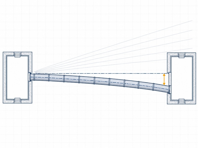
A small setting-out differential at the shaft is amplified along the drive, and the effect is easy to underestimate. A control-point error at the shaft is amplified by the same factor: the published example is a 1/8 in. (3 mm) differential across a 25 ft (about 7.6 m) shaft producing about a 5 in. (about 127 mm) lateral shift at 1,000 ft (about 305 m), converted at 1 in. = 25.4 mm and 1 ft = 0.3048 m, roughly forty times, so a small setting-out error at the shaft becomes a much larger offset at the far end of a long drive.
Setting out accurately at both shafts is therefore the cheapest accuracy improvement available on most drives.
Being out of tolerance triggers a defined response rather than a guess. A published utility specification requires excavation to stop immediately when the drive is out of tolerance, pending direction; in practice the response is to re-establish the reference with an independent survey, to correct gradually inside the permitted joint deflection, and, where the pipe duty allows, to accept the deviation and record it in the as-built alignment.
Steering Correction Discipline: Gradual, Never Abrupt
Published guidance is unambiguous that correction should be gradual: after the machine is pushed off line, make minor adjustments until it is gradually back on line and grade. An abrupt counter-steer is the one response that makes the deviation worse, because the pipe string cannot follow a sudden change of attitude.
- Correct early and gently. Small adjustments taken while the deviation is small keep the machine inside the joint deflection limit and avoid overcorrection.
- Never exceed the permitted joint deflection. The manufacturer’s angular limit at any joint is a hard stop, regardless of how much the machine could turn.
- Watch the whole string, not just the machine. The pipe behind the machine follows the bored hole, so a correction at the face takes time to propagate along the string.
- Keep a record. The reported position, the correction applied and the resulting movement should be logged so the response can be judged on data rather than memory.
This is why microtunneling grade control is as much discipline as technology. The guidance system can be excellent and the operator can still lose line by reacting too hard to a small error. Well-run drives feel boring from the surface: many small corrections that never look dramatic, and a machine that arrives within tolerance without an emergency at the reception shaft.
Frequently Asked Questions About Microtunneling Grade Control
How accurate can microtunneling grade control be?
Microtunneling accuracy can be as good as plus or minus 10 mm, and may be coarser where large diameter pipes are involved. That figure applies in favourable conditions; the practical envelope widens with depth, diameter, mixed ground and obstructions.
What is the difference between a laser target system and a gyro guidance system?
A laser target system projects a beam from the launch shaft to a target on the machine and is used to about 200 m with a minimum tunnel diameter of about 900 mm. A gyro guidance system is used for drives over 200 m and on curves, where the laser line of sight cannot be maintained. The practical switching rule is to keep the laser target system while the beam can be seen to about 200 m, and to use a gyro guidance system for drives over 200 m and on curves, with audit campaigns between 120–170 m from the drive start and 100 m from the finish on man-entry drives.
How often should the machine position be checked?
The position of the microtunneling machine should be checked and recorded at least twice per installed pipe, and reported daily. If the drive is found to be out of tolerance, excavation stops immediately pending direction.
What is a steering correction?
A steering correction is a controlled change of the machine attitude to bring it back toward the reference line and grade. Corrections should be gradual, because an abrupt counter-steer after the machine has been pushed off line makes the deviation worse.
Where should survey control points be placed?
Survey control points should be placed away from the zone of ground movement, so that they do not move with the ground the tunnel is disturbing. A control point inside the settlement zone loses the very datum it is meant to provide.
Why does a small alignment error matter so much?
A small alignment error measured at the shaft is amplified along the drive. Because the same amplification applies to the setting-out itself, the shaft reference marks are checked against an independent control point before the machine is launched, and the check value is recorded with the as-built records.
Key Takeaways
- Microtunneling grade control is a closed loop: measure the machine, compare with the reference alignment, correct gently, and repeat.
- A grade control plan is specified rather than improvised: the reporting interval, the check frequency, the correction limit and the gyro audit trigger are agreed before launch.
- Accuracy as good as ±10 mm has been reported in favourable, uniform ground and degrades with diameter, depth, mixed faces and obstructions; the figure that governs is the tighter of the pipe’s duty tolerance and the manufacturer’s permitted angular deflection at each joint.
- A laser target system suits drives to about 200 m and a minimum tunnel diameter of about 900 mm; a gyro guidance system covers drives over 200 m and curves, with audit campaigns on long man-entry drives.
- Guidance should report at intervals no longer than 2 seconds, and the machine position should be checked at least twice per installed pipe.
- Survey control points belong outside the zone of movement, because a small shaft setting-out error is amplified along the drive.
- Every value here is an input to project-specific design, not a substitute for it; a competent engineer must confirm the guidance method and achievable accuracy for the actual drive.
How JSW Supports Microtunneling Grade Control and Steering Accuracy
JSW — это компания, специализирующаяся на проектировании и строительстве трубопроводов, которая осуществляет бестраншейную прокладку трубопроводов собственными силами и с использованием собственного оборудования. В сферу нашей деятельности входят строительство методом микротуннелирования, other бестраншейные технологии и pipeline inspection service, alongside услуги по прокладке трубопроводов и horizontal directional drilling services for water, oil and gas and infrastructure owners.
We set microtunneling grade control plans against the ground and the machine we will actually use, not against a catalogue figure. Guidance system, reporting interval, check frequency and correction limits are agreed in the design, and the as-built line and grade are documented and handed over in a reviewable form. Pricing is risk-explicit, so an owner can see what drives precision and what carries contingency.
- Комплексная доставка: design, shaft construction, jacking and reception under one accountable team.
- Auditable guidance records: reported position, correction applied and survey checks handed over for review.
- Ценообразование с учетом риска: guidance, ground and curvature risk identified and priced openly.
- Safety and compliance: drives planned around OSHA and HSE expectations and the named pipe and jacking standards.
Need a grade control plan you can defend on a tight-tolerance drive? Send your alignment, drive length, diameter and ground investigation for a free technical review. Our engineers respond with a scoped recommendation, the shaft setting-out and guidance checks we expect to govern grade control on your drive, and a budget range.





































 English
  Arabic
  Russian
  Spanish
  French
  Vietnamese
  Polish
  Thai
Thai  Indonesian
  Turkish
  Portuguese