
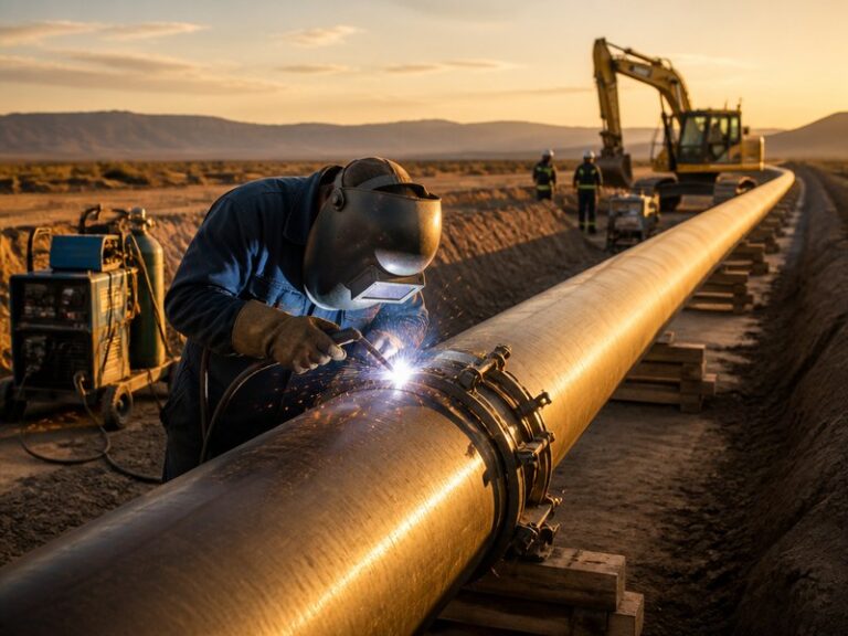
Pipeline welding is the process of joining pipe sections end to end with a continuous fused metal joint that contains the full operating pressure of the line. The joint must be free of cracks and voids, because a failed girth weld (the circumferential joint between two pipe ends) releases the line pressure at a single point. This guide explains the main processes and techniques used on oil and gas lines, the standards and welder qualifications that govern quality, and the defects inspectors look for, so you can understand how a welded pipeline is built, inspected, and kept safe in service.
Key Takeaways
- Definition: Welded girth joints join pipe sections with a full-penetration weld that must contain the full operating pressure of the line for decades.
- Processes: SMAW, GTAW, FCAW, SAW, and mechanized systems cover almost all field welding work, each with a defined role.
- Techniques: Downhill welding with cellulosic electrodes is the standard for cross-country lines; uphill welding is used for thick walls and critical tie-ins.
- Standards: API 1104 governs the field welding of pipelines designed to ASME B31.4 and ASME B31.8, and welders must be qualified before production work starts.
- Defects: Most weld rejections come from a short list of preventable defects, driven by joint cleanliness, preheat, technique, and interpass discipline.
What Is Pipeline Welding?
Pipeline welding is the controlled fusion of two pipe ends to form a continuous, pressure-tight joint. A girth weld is the circumferential weld that joins two pipe ends, and a long mainline can contain tens of thousands of them. The weld must achieve full penetration through the pipe wall and be free of cracks and voids, because a girth weld on a transmission line can be the only thing standing between the transported fluid and the environment for 30 to 50 years of service.
Line pipe is typically carbon steel to API 5L grades from X42 to X80, with wall thicknesses from about 6 mm (0.24 in) to more than 25 mm (1 in) on large-diameter lines. Stainless steel and duplex steels appear in offshore risers and corrosive service. Pipe welding is the general term for joining pipe in any context, from plant fabrication to process piping. Pipeline welding is the field-specific term for joining transmission and distribution lines under dedicated standards, mainly API 1104 for lines designed to ASME B31.4 or B31.8, whereas plant piping to ASME B31.3 is qualified to ASME Section IX. Pipe welding is used at every stage of the asset life cycle: mainline girth welds, tie-ins, branch connections, fittings, and repair.
The scale of the industry explains why the process is so closely controlled. Oil and gas transmission networks total an estimated 3 million kilometers worldwide, and in the United States alone about 2.6 million miles of gas distribution, gas transmission, and hazardous liquid pipelines are in service per PHMSA 2024 data, nearly all of it joined by welds. A defective weld can leak or rupture years after installation, which is why the industry treats the welded joint as the single most integrity-critical element of pipeline construction.
Why Does Weld Quality Matter on a Pipeline?
Weld quality decides whether a pipeline stays in service or fails. A girth weld must transfer the full axial load of the line and contain the fluid pressure without leaking for the design life of the asset, which is why construction specifications require qualified procedures, qualified welders, and non-destructive examination of a defined percentage of welds.
Per PHMSA incident data (2024), weld-related and material failures account for a small share of reportable pipeline incidents, but their consequences are out of proportion to their numbers: a failed girth weld releases the full line pressure at a single point. In our experience across pipeline construction and repair projects, the majority of weld rejections come from a short list of preventable defects that this guide covers in detail.
Quality also drives economics. A single rejected weld consumes repair time, inspection time, and the crew’s schedule, and on a large-diameter line one rejection can stop the spread for a full shift. Getting the welding process right the first time is cheaper than repairing it, every time.
How Does the Pipeline Welding Process Work? Step by Step
Every pipeline welding process follows the same sequence: bevel and clean the joint, align and tack it, preheat, weld the root, fill and cap the groove, and prove the weld with inspection. The details change with process and material, but the steps do not.
- Joint preparation. Pipe ends are beveled, typically to a 30-degree bevel with a 1.5 mm (0.06 in) root face, then cleaned of rust, oil, and moisture. Where the route requires a change of direction, field bends are made with pipeline cold bending instead of welded fittings, and long pipe is cut to length with pipeline cutting machines before beveling.
- Alignment and tacking. External or internal line-up clamps hold the two ends to the specified root gap. Tack welds fix the joint in place, and internal clamps double as the guide for the first pass on large diameters.
- Preheat. Carbon steel is preheated to the range in the welding procedure specification, commonly 100 to 150 degrees Celsius (210 to 300 degrees Fahrenheit) measured at the joint, to drive off moisture and slow the cooling rate. Preheat is the primary defense against hydrogen cracking in high-strength line pipe.
- Root pass. The first pass seals the inside of the joint. Cellulosic electrodes such as E6010, or GTAW with backing gas, are the common choices. The root must show full penetration and a smooth internal profile.
- Fill and cap passes. Subsequent passes build the weld to full wall thickness. Low-hydrogen electrodes, FCAW, or GMAW are typical, and every pass is cleaned of slag before the next one is deposited.
- Inspection. The finished weld is examined by non-destructive testing per the governing standard and the project specification, typically radiography or automated ultrasonic testing on mainlines, plus magnetic particle or penetrant testing where required.
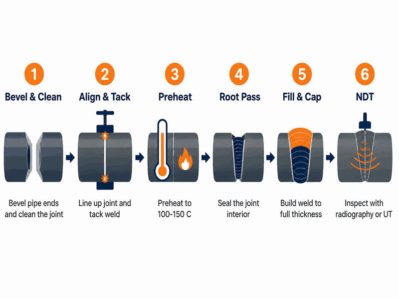
Figure 1. Six steps of the girth-weld sequence, from beveling and alignment to non-destructive inspection of the finished joint.
On a typical construction spread, the root and hot pass (the second pass laid immediately after the root) are completed with one crew and the fill and cap passes with a second crew, so the spread keeps moving. On a 2025 24-inch gas transmission line project, our crews welded the root with E6010 and filled with self-shielded FCAW, completing about 30 joints per day per crew with an acceptance rate above 98 percent after automated ultrasonic testing.
What Are the Main Types of Pipeline Welding?
Five arc welding processes cover nearly all field girth welding work. Knowing the types of pipeline welding available is the first step in process selection, and the choice depends on pipe size, wall thickness, location, and the productivity the schedule demands.
| Процесс | How it works | Typical use | Strengths | Ограничения |
|---|---|---|---|---|
| SMAW (stick welding) | Covered electrode melts to form the weld; cellulosic for root and hot pass, low-hydrogen for fill and cap | Manual field girth welds, tie-ins, repairs | Simple equipment, works outdoors in wind, tolerant of surface condition | Slow deposition, slag between passes, operator dependent |
| GTAW (TIG welding) | Tungsten electrode with separate filler rod, inert gas shielding | Root passes, stainless and duplex pipe, small-diameter lines | Highest quality, precise control, no slag | Slow, needs clean conditions and skilled labor |
| GMAW / FCAW (wire welding) | Continuous wire with gas shielding, or self-shielded flux-cored wire | Semi-automatic fill and cap on larger lines | High deposition, consistent quality | Heavier equipment, wind affects gas shielding, higher heat input |
| SAW (submerged arc welding) | Arc burns under a blanket of granular flux | Double-jointing in pipe yards, long straight runs of large diameter | Very high deposition, mechanized quality | Fixed-position work only, flux handling, slag removal |
| Mechanized / automatic welding | Internal line-up clamps and external welding bugs with RMD (regulated metal deposition), STT (surface tension transfer), or orbital TIG | Long mainline runs, high-specification projects | Consistent quality, high speed, removes welder fatigue | High capital cost, needs automated inspection, less flexible |
For most cross-country construction, the practical combination is stick welding for the root and hot pass with cellulosic electrodes, followed by low-hydrogen SMAW or semi-automatic FCAW for fill and cap. This mix keeps the equipment simple, tolerates outdoor conditions, and meets the deposition rates a mainline schedule needs.
Need a qualified API 1104 crew for your next spread? Contact our welding engineers at sales@jsw.com or request a quote, and we will confirm the process, the procedure, and the inspection scope for your pipe size and governing standard.
Pipeline Welding Techniques: Downhill vs Uphill and Positions
Two pipeline welding techniques dominate field work: downhill and uphill. The direction of travel changes the heat input, the bead profile, and the speed, and experienced crews use both on the same project.
- Downhill welding (stovepipe): The welder travels from the top of the pipe toward the bottom. Cellulosic electrodes burn hot and fast, giving a shallow, quick pass. This is the standard technique for cross-country mainline welding because the root and hot pass are completed in a single sequence and the spread moves fast. Root beads typically run 3 to 5 mm (0.12 to 0.2 in) thick.
- Uphill welding: The welder travels from the bottom toward the top. Low-hydrogen electrodes deposited with a weave give thicker beads and more heat input. Uphill is used for thicker walls, higher-strength steels, and critical tie-ins where penetration and toughness matter more than speed.
| Аспект | Downhill (stovepipe) | Uphill |
|---|---|---|
| Travel direction | Top of pipe to bottom | Bottom of pipe to top |
| Typical electrodes | Cellulosic (E6010, E7010) | Low-hydrogen (E7018 and above) |
| Speed | Fast; root and hot pass in one sequence | Slower; thicker beads per pass |
| Идеально подходит для | Cross-country mainline girth welds | Thick walls, high-strength steel, critical tie-ins |
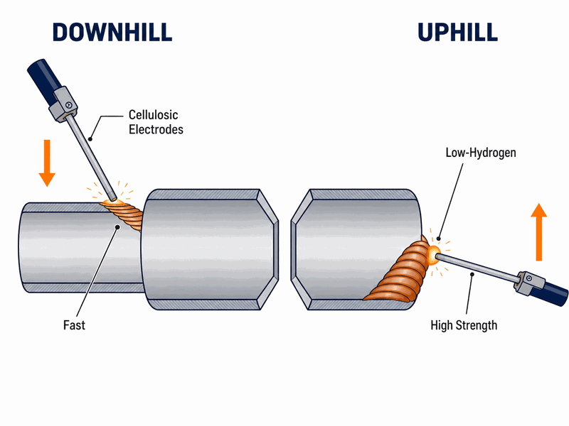
Figure 2. Downhill travel with cellulosic electrodes is the field standard for mainline welding, while uphill travel with low-hydrogen electrodes serves thick walls and critical tie-ins.
Welding positions are described with the pipe fixed at defined angles. In the 1G position the pipe rolls, in 2G the axis is vertical, in 5G the pipe is fixed horizontal, and in 6G the pipe is fixed at 45 degrees. The 6G position is the qualifying position for pipeline welders because it combines every position in one test. Most pipeline welder qualification tests, including the API 1104 Chapter 6 test, are conducted in this position so the qualification covers every field position.
Common Pipeline Welding Defects and How to Prevent Them
Nearly all rejected welds come from a short list of pipeline welding defects, and each one has a known cause and a known prevention. Defects are either surface and shape related, found by visual, magnetic particle, or penetrant testing, or volumetric, found by radiography or ultrasonic testing.
| Defect | Cause | Prevention |
|---|---|---|
| Porosity | Moisture, contamination, wrong shielding gas flow | Dry and clean the joint, apply preheat, verify gas flow |
| Slag inclusion (entrapment) | Slag trapped between passes | Remove slag completely between passes |
| Incomplete fusion | Low heat input, wrong technique, poor access | Correct parameters, proper angle and manipulation |
| Lack of penetration | Root gap too small, root face too large | Match bevel and gap to the welding procedure specification |
| Undercut | Excessive current or travel speed | Control amperage and arc time at the weld toes |
| Concavity (suck-back) | Root bead pulled inward by arc pressure | Lower root current, adjust gap, use backing gas |
| Hydrogen cracking | Moisture plus high-strength steel plus fast cooling | Preheat, low-hydrogen electrodes, dry electrode storage |
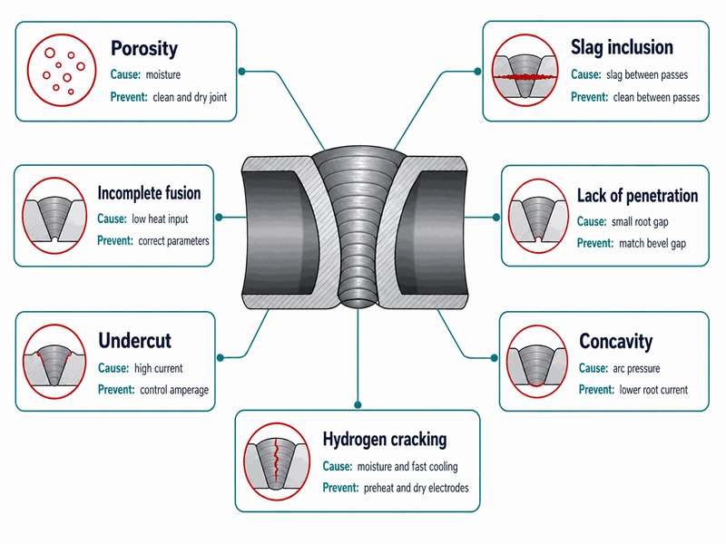
Figure 3. Porosity, slag inclusion, and hydrogen cracking dominate weld rejections; each defect has a known cause and a known prevention.
In our welding department we track every rejection across projects. Porosity and slag inclusion account for more than half of all rejected girth welds, and both are eliminated by discipline: clean steel, dry electrodes, and complete interpass cleaning. We also see hydrogen cracking on X70 and X80 pipe when preheat is skipped, which is why our welding procedure specifications always state the measured preheat and interpass temperature on the job card.
When a weld is rejected, the repair follows a documented procedure and is re-inspected to the same acceptance standard. Our pipeline repair services cover weld repairs, sleeve repairs, and defect assessment on lines both new and in service.
Pipeline Welding Standards and Welder Certification
Field welding of pipelines is governed by standards that define how welds are made, qualified, and accepted. The welding standard and the design code play different roles, and both are written into the project specification.
- API 1104 (Welding of Pipelines and Related Facilities) is the field welding standard for cross-country pipelines. It covers welding procedure qualification in Chapter 4, welder qualification in Chapter 6, and acceptance criteria for radiography, ultrasonic testing, magnetic particle testing, and penetrant testing.
- ASME B31.4 and ASME B31.8 are the design codes for liquid and gas pipeline systems. Both adopt API 1104 as the welding standard within their scope.
- ASME Section IX is the qualification standard used where plant piping to ASME B31.3 is welded. A qualification under Section IX does not transfer to API 1104 pipeline work.
- Regulations administered by the U.S. Pipeline and Hazardous Materials Safety Administration (PHMSA), including 49 CFR Part 192 for gas and Part 195 for hazardous liquids, add federal requirements in the United States; other countries apply their own national rules.
Understanding the pipeline welding standards that govern your project is the first step in building a compliant specification. A welder qualified to API 1104 must pass a 6G test with a defined electrode class, thickness range, and process, and the qualification is recorded with its essential variables. The same logic applies to automatic pipeline welding: the procedure, the machine settings, and the operator must be qualified within the governing system before production work starts.
Welding procedure qualification (WPS and PQR) and welder qualification are the two documents inspectors ask for first, and every production weld must be backed by an approved welding procedure qualification before the first joint is welded. We keep both on file for every process we run, and we requalify whenever an essential variable changes.
Automatic and Mechanized Welding
Mechanized and automatic welding systems now complete a large share of mainline girth welds on long-distance projects. Instead of a welder’s hand, a machine carriage holds the torch or electrode and travels around the pipe at a controlled speed with repeatable parameters.
Two configurations dominate. Internal line-up clamps carry welding heads inside the pipe for the root pass, then external bugs complete the fill and cap. External bug-and-band systems run on a band around the pipe and are used for all passes, including tie-ins. Common process choices are RMD (regulated metal deposition) and STT (surface tension transfer) for the root and pulsed GMAW or orbital TIG for fill and cap.
Mechanized systems typically deposit filler metal at two to three times the rate of manual stick welding on large-diameter lines, and because the parameters are machine controlled, weld-to-weld consistency is far higher. The trade-offs are capital cost, the need for automated ultrasonic testing instead of film radiography, and less flexibility when conditions change. On a 2025 30-inch mainline project, our automatic crew sustained about 60 joints per day with a first-run acceptance rate above 99 percent, roughly double the output of a manual crew on the same spread.
The automatic pipeline welding decision is a project-level one: for long, straight runs with consistent wall thickness, automation wins on speed and quality; for short tie-ins, repairs, and field connections, manual welding is usually the practical choice.
On our own spreads, the automatic pipeline welding machine is qualified as part of the welding procedure: machine settings and operator qualification are recorded as essential variables, and the acceptance standard is identical to manual welds. That is how we keep the same inspection criteria no matter which process the project calls for.
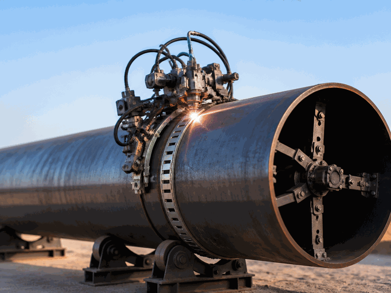
Figure 4. Automatic pipeline welding system on a large-diameter line, combining an internal line-up clamp for the root pass and external welding bugs for fill and cap.
How to Choose the Right Welding Process
Choosing among the types of pipeline welding comes down to five factors: the pipe, the location, the material, the specification, and the schedule.
- Pipe diameter and wall thickness: thick walls favor low-hydrogen stick welding or FCAW; thin walls favor TIG roots.
- Расположение: remote spreads favor stick welding and self-shielded wire processes because they tolerate wind; yards and stations can use gas-shielded processes and SAW.
- Материал: carbon steel line pipe is the default; stainless and duplex require GTAW and stricter cleanliness control.
- Governing standard and client specification: the specification may mandate a process, an NDT method, or a minimum level of automation.
- Productivity and schedule: mechanized systems pay for themselves above a threshold number of joints; below it, manual crews are cheaper.
When the schedule is short and the line is long and uniform, we propose mechanized welding with automated ultrasonic testing. When the job is a handful of tie-ins on an existing line, we propose manual stick or TIG welding with radiography. Matching the types of pipeline welding to the job is how you control both quality and cost.
Once the process is decided, execution quality depends on the procedure and the crew. Our pipeline construction services cover the full scope from code selection through final testing, so the chosen welding process is executed under the standard that governs your project.
What Drives the Cost of a Welded Pipeline?
Welding cost is driven by consumables, labor, equipment, inspection, and the repair rate. Each factor interacts: cheaper electrodes can cost more in the end if they raise the rejection rate.
- Consumables: electrodes, wire, shielding gas, and grinding wheels.
- Трудовые ресурсы: crew size and welder productivity; mechanized crews cost more per hour but weld faster.
- Оборудование: pipeline welding machines, line-up clamps, internal clamps, and automated inspection systems.
- Осмотр: the NDT percentage is usually specified, from 10 percent to 100 percent radiography or automated ultrasonic testing; higher percentages find defects early but add cost.
- Repair rate: the largest hidden cost; one repair weld consumes crew time, consumables, inspection, and schedule.
On a typical cross-country project, welding and its inspection account for a double-digit share of total installed pipeline cost, and a rejected weld costs several times the price of a first-time weld because of the full re-inspection cycle. In our cost models, reducing the repair rate from 5 percent to 1 percent saves more than the cost of upgrading the welding process. For an estimate on your specific pipe size, route, and inspection scope, ask our team to model your project cost before you commit to a process.
Welding Safety on Pipeline Sites and In-Service Work
Welding on a pipeline is hot work, often on or near pressurized systems, and the safety rules are non-negotiable. The hazards are burns, fumes, fire, and, on operating lines, the line itself.
- Hot work permits, a fire watch, and extinguishers at every joint.
- Ventilation and fume extraction in trenches and confined areas.
- Personal protective equipment: welding helmet, flame-resistant coveralls, and gloves; hydrogen sulfide monitoring on sour service.
- Electrical safety and proper grounding of the welding machine.
In-service welding on a line that is in operation adds two risks: burn-through and hydrogen cracking. In-service welding guidance is defined in ASME PCC-2 and API 1104: the weld is made with controlled heat input to keep the internal wall temperature below the point where the fluid or the wall is damaged. This is the discipline behind hot tapping, welding a fitting onto a live line and then cutting the opening through the fitting. Every hot tap we execute follows a written in-service welding procedure with heat input limits and continuous temperature monitoring, supported by hot tapping equipment and line stopping and plugging equipment matched to the line size and pressure class.
For pipelines that cannot be taken out of service, our hot tapping and plugging services combine the welding procedure, the fittings, and the mechanical isolation in one controlled operation, and pipeline maintenance services keep the integrity program running between projects.
Часто задаваемые вопросы
What is pipeline welding?
It is the process of joining pipe sections end to end with a continuous fused metal joint. The weld must achieve full penetration through the pipe wall and be free of cracks and voids, because a girth weld on a transmission line carries the full operating pressure of the transported fluid for the design life of the asset.
What is the difference between pipe welding and pipeline welding?
Pipe welding is the general term for joining pipe in any context, including plant fabrication and process piping. Pipeline welding, in contrast, refers specifically to the field welding of transmission and distribution lines, governed by dedicated standards, mainly API 1104 for pipelines designed to ASME B31.4 or ASME B31.8.
What is the best welding process for pipelines?
There is no single best process. Stick welding with cellulosic electrodes is the standard for manual field roots and hot passes, low-hydrogen SMAW or FCAW handles fill and cap passes, and mechanized systems with RMD, STT, or orbital TIG dominate long mainline runs where speed and consistency matter. The governing standard and the project specification decide what is acceptable.
What does 6G mean in pipeline welding?
6G is the welding position in which the pipe is fixed at a 45-degree angle and the welder must weld around the joint, covering all positions in one test. Most pipeline welder qualification tests are conducted in this position so the qualification covers every field position.
Do pipeline welders need a certification?
Yes. Pipeline welders must be qualified before production work, typically to API 1104 Chapter 6 for cross-country lines or to ASME Section IX for plant piping. The qualification records the process, electrode class, thickness range, and position, and it must match the scope of the job.
Can a pipeline be welded while it is in service?
Yes, with a qualified in-service welding procedure. Hot tapping and pipeline repair welding on operating lines follow the guidance of ASME PCC-2 and API 1104, with controlled heat input to prevent burn-through and to manage the cooling rate of the weld.
What is downhill welding used for?
Downhill welding is the standard technique for cross-country mainline welding. The welder travels from the top of the pipe downward with cellulosic electrodes, producing fast, shallow passes that allow the root and hot pass to be completed in one sequence. Uphill welding is reserved for thicker walls, higher-strength steels, and critical tie-ins.
If you are planning a new line, a tie-in, or a repair, the fastest way to de-risk your project is to bring in qualified welders with approved procedures before the first joint is made. JSW supplies API 1104-qualified welding crews for construction, repair, and in-service work, including hot tapping and line stopping, and our engineers confirm the governing standard, the welding procedure, and the inspection scope for your pipe size and fluid. Talk to our welding engineers for a project-specific answer.
Pipeline welding is what turns individual pipe sections into a single pressure-tight line, and the quality of that joint determines whether the line stays safe for decades. This guide has covered the definition of the process, the step-by-step pipeline welding process, the main processes and techniques from SMAW and GTAW to mechanized systems, the pipeline welding standards that govern quality, the defects inspectors look for, and the cost and safety factors that shape every project.
Whether you are planning a new line, a tie-in, a station, or a repair on an operating pipeline, the right result starts with the right procedure and the right crew. Our pipeline repair services handle weld and sleeve repairs on operating pipelines and on new lines. Where trenchless methods fit the route better, we also execute horizontal directional drilling, microtunneling, and trenchless pipeline repair.
Get a compliant welding quotation. JSW provides pipeline welding services for new mainline construction, tie-ins, and repair work, with welders qualified to API 1104 and welding procedure specifications approved before the first joint is welded.
Send us your pipe size, fluid, pressure, and governing code, and our engineers will confirm the compliant approach and provide a quotation.





































 English
  Arabic
  Russian
  Spanish
  French
  Vietnamese
  Polish
  Thai
Thai  Indonesian
  Turkish
  Portuguese