

Quick Answer
- Typical HDD pullback force: about 10,000 to 500,000+ lb (4.5 to 227+ t), with most mid-size pipeline installations between 20,000 and 100,000 lb (9 to 45 t).
- For HDPE pipe, a practical planning rule of thumb is roughly 1,000 to 1,500 lb of pullback force per inch of pipe diameter.
- The accepted framework for calculating HDD pullback force is ASTM F1962 (current edition), which sums pipe friction, fluid drag, capstan and entry-exit drag and checks the total against the pipe’s allowable pull force.
Typical HDD pullback force ranges from about 10,000 lb (4.5 t) for small utility bores to more than 500,000 lb (227 t) for large-diameter, long-distance crossings, and most mid-size pipeline installations fall between 20,000 and 100,000 lb (9 to 45 t). It is written for pipeline engineers, contractors and owners planning trenchless pipeline installations.
In this guide:
- Why pullback force governs both machine and pipe selection.
- Planning values by pipe size and material.
- The four components behind every pullback force estimate and the ASTM F1962 calculation method.
- How to match rig pullback capacity to your bore plan, plus field measures that lower the load.
What Does HDD Pullback Force Mean?
In horizontal directional drilling (HDD), pullback force is the tensile load the drill rig applies to the drill string as it draws the product pipe back through the reamed borehole. It is the final stage of the HDD process: after the pilot hole is drilled and reamed to the required diameter, the pipe string is attached behind the reamer with a swivel and pulled from the exit pit back to the rig, becoming the installed pipeline.
Pullback force matters because it is the only load that stresses the product pipe itself during installation. The rig must be able to generate it, and the pipe must be able to survive it without permanent deformation. In our field experience, the pullback stage is where HDD projects most often go wrong, either because the rig runs out of capacity near the end of the pull, or because the pipe is loaded beyond its tensile limit and is stretched, buckled or ovalized beyond repair.
- Units: pullback force is measured in pounds (lb), tonnes (t) or kilonewtons (kN); 1 t is roughly 2,205 lb.
- Read point: the driller monitors it on the rig load gauge, and project engineers often add a load cell at the swivel for a second, independent reading.
- Peak timing: force climbs as more pipe enters the hole and is highest in the final section of the pull, not at the start.
- Design basis: for polyethylene pipe, ASTM F1962 (current edition), the standard guide for maxi-HDD placement of PE pipe, is the accepted framework for estimating and limiting pullback force.
Typical Pullback Force Values by Pipe Size
No single number applies to every bore, but planning ranges are well established. For HDPE pipe in moderate ground with properly conditioned drilling fluid, a practical rule of thumb widely used in HDD planning is roughly 1,000 to 1,500 lb of pullback force per inch of pipe diameter, for bores in the 1,000 to 2,500 ft (300 to 800 m) range. The table below summarizes the typical HDD pullback force ranges we use for early machine selection.
| Nominal pipe diameter | Typical HDD pullback force (HDPE, planning range) | Typical rig class |
|---|---|---|
| 4 in (100 mm) | 4,000-8,000 lb (2-4 t) | Mini |
| 6 in (150 mm) | 6,000-12,000 lb (3-5 t) | Mini |
| 8 in (200 mm) | 9,000-16,000 lb (4-7 t) | Mini |
| 12 in (300 mm) | 12,000-25,000 lb (5-11 t) | Midi |
| 16 in (400 mm) | 20,000-40,000 lb (9-18 t) | Midi |
| 24 in (600 mm) | 30,000-70,000 lb (14-32 t) | Midi to maxi |
| 36 in (900 mm) | 50,000-110,000 lb (23-50 t) | Maxi |
Planning basis: moderate ground, conditioned drilling fluid and bore lengths of about 1,000 to 2,500 ft (300 to 800 m). Longer, harder or more curved bores sit at or above the top of each range.
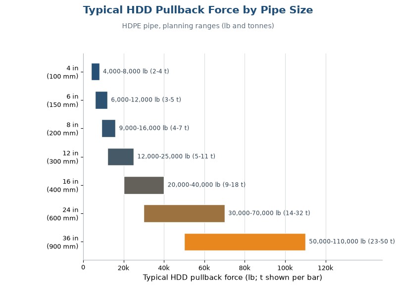
Figure 1. Typical HDD pullback force planning ranges for HDPE pipe by nominal diameter.
These values are planning estimates, not guarantees. Actual pullback force scales with bore length, soil type, mud condition, curvature and pipe weight, so a 12 in pipe in a short sandy bore may pull at 10,000 lb while the same pipe in a long clay bore with tight bends can require 35,000 lb. Steel pipe is heavier and usually needs buoyancy control, which raises the required force: for large-diameter steel river crossings of 24 to 48 in, pullback forces documented in published HDD case histories commonly reach 200,000 to 600,000 lb (90 to 270 t), and the largest maxi rigs are rated near 1,300,000 lb (600 t) for exactly these jobs.
What Determines Pullback Force? The Four Components
Every HDD pullback force estimate is the sum of four resistances that act while the pipe is being pulled. Understanding these four components is the foundation of the ASTM F1962 design model used in horizontal directional drilling (HDD).
- Pipe friction: the sliding resistance between the pipe and the borehole wall, equal to the effective pipe weight in the mud times the friction coefficient (mu). Friction coefficients of 0.15 to 0.35 are typical with well-conditioned mud; dry or collapsed holes push this much higher.
- Fluid drag: the resistance of drilling fluid flowing past the pipe surface, which depends on mud viscosity, the annulus gap between pipe and hole, and pull speed.
- Capstan effect: around curves in the bore path, tension multiplies exponentially (see the capstan equation in the calculation section below). A few gentle bends add little; tight bends add a lot.
- Entry and exit drag: the pipe rubbing against roller stands and the soil at the entry ramp before it enters the borehole, plus soil pressure near the entry and exit points.
| Компонент | Main drivers | Typical share of the total | Field measures that reduce it |
|---|---|---|---|
| Pipe friction | Effective pipe weight in mud, friction coefficient, contact length | 40-60 percent | Conditioned lubricating mud, adequate overcut, staged reaming |
| Fluid drag | Mud viscosity, annulus gap, pull speed | 20-40 percent | Hold pull speed at 1 to 3 m/min, keep the annulus open |
| Capstan effect | Bend angle and tension at each curve | 0-30 percent, rising sharply with tight bends | Flatter bore geometry, no sharp curves near the pipe |
| Entry and exit drag | Roller support, ramp angle, soil at the pits | 5-15 percent | Roller stands, lubricated entry ramp, clean pits |
Shares vary widely by project and are not additive.
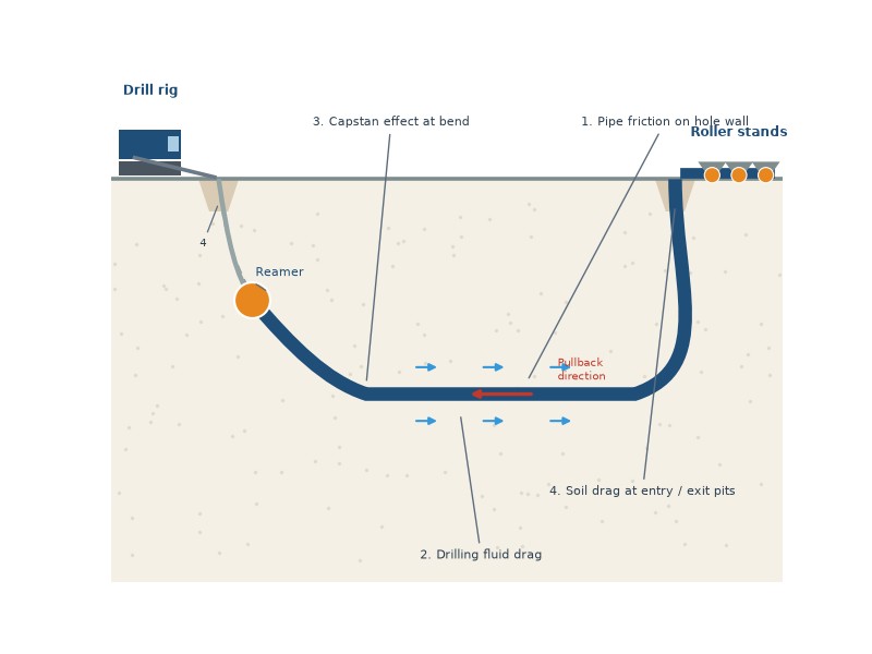
Figure 2. The four components that make up total pullback force.
In our pullback monitoring on a 600 mm (24 in) HDPE water main crossing, the force rose from about 12 t (26,500 lb) when the pipe nose entered the hole to 34 t (75,000 lb) as the final third of the string was pulled in. Our predicted peak was 30 t, so the measured value landed about 13 percent above prediction, within the 10 to 15 percent band we treat as normal for a healthy pull. Watching this curve against the predicted values is how a crew knows the bore is healthy or the mud is failing.
How to Calculate Pullback Force: The ASTM F1962 Method
The accepted way to calculate HDD pullback force is the model in ASTM F1962 (current edition), which estimates the total pull force for PE pipe by summing the friction, fluid drag, capstan and soil-load components along the designed bore path. The same component logic is used by most proprietary and online HDD pullback force calculators, and it is a five-step process.
Core equations behind every HDD pullback force estimate:
- Friction force: F = mu x W’ x L, where mu is the friction coefficient, W’ is the effective pipe weight in the mud and L is the segment length.
- Capstan amplification: T2 = T1 x e^(mu x theta), where theta is the bend angle in radians.
- Allowable pull force: F_allow = sigma x A, where sigma is the allowable installation tensile stress (about 1,000 psi for PE pipe) and A is the pipe wall cross-sectional area.
- Define the bore path and the geotechnical profile, including soil type, groundwater and curvature at every bend.
- Calculate the effective weight of the pipe in the drilling fluid, accounting for buoyancy. PE pipe is nearly weightless or even buoyant in 9 to 10 lb/gal mud, while steel pipe displaces less of its weight and stays heavy.
- Estimate frictional drag per segment as the effective pipe weight times the friction coefficient times segment length.
- Add fluid drag and apply the capstan amplification around each bend, working from the exit side toward the rig.
- Compare the total required pullback force with the allowable force: for PE pipe, installation tensile stress is commonly limited to about 1,000 psi (6.9 MPa), which for a 12 in DR 11 pipe equals roughly 42,000 lb of allowable pull force.
A worked example: a 12 in DR 11 HDPE pipe across 1,000 ft of moderate soil with one 30-degree bend and good mud. Pipe friction contributes about 4,000 lb, fluid drag about 8,000 to 12,000 lb, the capstan effect about 2,000 lb, and entry-exit drag about 2,000 to 4,000 lb. The total pullback force estimate is roughly 16,000 to 22,000 lb (7 to 10 t, 71 to 98 kN), which is 38 to 52 percent of the 42,000 lb allowable for this pipe, a comfortable but not trivial margin. For steel pipe, the same calculation is run against a tensile stress limit derived from yield strength; the allowed value is set by the design code for the project, commonly in the 50 to 90 percent of SMYS range for temporary installation cases, while in-service operating limits under B31.4 and B31.8 are typically near 72 percent of SMYS.
Need your HDD pullback force calculation reviewed? Send your bore plan to JSW’s engineering team for a free, no-obligation technical check within five working days.
How Pipe Material Affects Pullback Force
Material choice changes pullback force more than any other single design decision, because it determines how heavy the pipe is inside the borehole and how much tension it can safely carry. The comparison below reflects what we see across HDD projects.
| Материал трубы | Behavior in the borehole | Typical pull force vs HDPE |
|---|---|---|
| HDPE (PE 4710 / PE 100) | Near-buoyant in mud, low friction, high tensile capacity for its weight; the standard HDD material. | Baseline (1.0x) |
| Сталь | Heavy in mud; usually water-ballasted or weighted for buoyancy control, which raises required force. | 1.5x to 3x |
| Ковкий чугун | Heavy and stiff; requires careful joint protection and larger overcut; rarely used for long HDD bores. | 1.5x to 2.5x |
| PVC / conduit | Light but low tensile strength; pull limits are strict and joint integrity is the controlling factor. | Similar, but lower allowable |
HDPE dominates HDD installations precisely because of this combination: it floats in the drilling fluid, so friction stays low, and its allowable pull force is high relative to its weight. Steel is chosen when pressure, temperature or product requirements demand it, and the design must then account for ballasting, heavier rigs and higher pullback force throughout the pull. Water ballasting (flooding the string with water as it enters the bore) is used to control buoyancy and keep the pipe on a stable path, but the added weight raises the effective pipe weight in the mud, which directly increases friction and, with it, the required pullback force and rig class.
HDD Rig Pullback Capacity Classes and Matching the Machine
Rigs used for horizontal directional drilling are sold and specified by rated pullback capacity, and commercial lineups span roughly 8,000 lb for compact utility drills to more than 550,000 lb for pipeline-class machines, with the largest maxi rigs reaching about 1,300,000 lb (600 t). Matching the machine is a capacity question first and a torque and mud-pump question second.
- Mini rigs (5,000 to 25,000 lb): service lines, telecom and gas connections, pipe up to about 8 in, short bores.
- Midi rigs (25,000 to 100,000 lb): distribution mains and mid-size crossings, pipe from about 12 to 24 in.
- Maxi rigs (100,000 to 1,300,000 lb): large-diameter, long-distance and river crossings, pipe from about 24 in upward.
Classification boundaries vary between organizations: NASTT and DCA training materials often place the mini-rig ceiling near 100,000 lb. The ranges above follow the field-practice convention used in the planning table in this guide.
Our selection rule is to rate the rig at no less than 1.5 times the predicted peak HDD pullback force, and up to 2 times for uncertain ground or long steel strings. We also check that torque and mud pump flow meet the reaming and fluid plan, because a rig with enough pullback but not enough torque can stall halfway through the job. On a 36 in steel crossing we supported, the design pullback was about 320 t (705,000 lb), so the contractor was required to mobilize a rig rated at 500 t (1,100,000 lb) to hold the 1.6x margin; the monitored peak stayed within about 10 percent of the design value through the most demanding section of the pull.
How to Reduce Pullback Force in the Field
In horizontal directional drilling (HDD), pullback force is not a fixed number; the crew controls it every hour of the pull. These are the measures that consistently lower the load in our projects.
- Keep the drilling fluid conditioned and lubricating; viscosity, gel strength and hole cleaning all directly reduce friction and fluid drag.
- Ream the hole to a sufficient overcut, typically 1.3 to 1.5 times the pipe OD for HDPE and larger for steel, so the pipe is not squeezed against the wall.
- Use staged reaming passes to enlarge the pilot hole gradually instead of one oversized pass.
- Support the pipe string on roller stands and guide it into the entry angle so it does not drag on the ground.
- Install a swivel between the reamer and the pipe so rotation is not transferred into the string.
- Control pull speed, normally 1 to 3 m/min (3 to 10 ft/min), because faster pulls increase fluid drag sharply.
- Finish the pipe string to fabrication quality before the pull: butt-fused or welded joints, clean surfaces and proper roller support at the entry. Good pipe string fabrication shows up directly as a stable, low force curve.
- Monitor force continuously and stop the pull if the load climbs above the predicted value plus margin; restarting after a stop takes more force than a steady pull, so plan for no unnecessary stops.
Pullback Force FAQ
How much pullback force is needed for HDD?
For most horizontal directional drilling (HDD) installations, the required pullback force falls between 10,000 and 100,000 lb (4.5 to 45 t, 44 to 445 kN). Small utility bores with pipe under 8 in typically need less than 15,000 lb, mid-size pipeline crossings of 12 to 24 in typically need 15,000 to 70,000 lb, and large-diameter steel river crossings can need several hundred thousand pounds.
What is the pullback force for HDPE pipe by size?
Typical HDD pullback force values for HDPE pipe by size are listed in Table 1: 4 in pipe usually pulls at 4,000 to 8,000 lb, 8 in at 9,000 to 16,000 lb, 12 in at 12,000 to 25,000 lb and 24 in at 30,000 to 70,000 lb under moderate ground and conditioned mud. Longer bores, clay ground or tight bends push these values toward the top of each range.
How is HDD pullback force calculated?
The standard method, based on the ASTM F1962 model, sums four components: frictional drag between the pipe and the borehole, drilling fluid drag, the capstan effect at bends, and entry-exit soil drag. The total is then checked against the pipe’s allowable tensile force, which for PE is usually based on a 1,000 psi installation stress limit.
What is the maximum allowable pull force for HDPE pipe?
The allowable pull force for HDPE depends on wall thickness and material grade. Using the common 1,000 psi tensile stress limit, a 12 in DR 11 pipe allows roughly 42,000 lb, and a 24 in DR 11 pipe allows roughly 150,000 lb. Good designs keep the required pullback force at 50 to 70 percent of the allowable value.
What size HDD rig do I need?
Calculate the predicted peak pullback force first, then select a rig rated at 1.5 to 2 times that value. A 20,000 lb predicted load therefore points to a 30,000 to 40,000 lb class midi rig, and a 100,000 lb predicted load points to a 150,000 to 200,000 lb class maxi rig. Verify torque and mud pump capacity as well.
Why does pullback force increase during the pull?
Because the resisting length grows as the pipe enters the hole. At the start only the nose is in the borehole; at the end the full string is inside, so friction and fluid drag act over the entire length. This is why the peak HDD pullback force is always expected near the end of the pull, not the beginning.
Can drilling fluid reduce pullback force?
Yes, in two ways: it lubricates the pipe-to-hole contact, lowering the friction coefficient, and its density provides buoyancy that reduces the effective pipe weight. The trade-off is that excessive mud pressure can cause frac-out at the surface, so fluid density and pressure are managed within the geotechnical limits of the crossing.
What happens if pullback force exceeds the pipe’s capacity?
HDPE can stretch permanently, neck down or lose wall thickness at connections; steel can exceed yield and buckle at bends. Both failures are usually detected too late to reverse, which is why continuous force monitoring against a pre-calculated allowable is a standard requirement on disciplined HDD projects.
Planning a directional crossing and want a second opinion on your pullback force estimate? Send your bore plan to JSW’s engineering team and we will return a technical review within five working days.
How JSW Supports HDD and Pipeline Projects
JSW is a pipeline engineering and construction partner supporting owners and contractors across the full lifecycle of directional drilling and trenchless work. We provide pipeline construction services, trenchless pipeline repair technology and pipeline maintenance services, alongside specialized capabilities that HDD projects depend on, including pipeline automatic welding technology, pipeline cold bending and pipeline hot tapping and plugging services. Our teams also supply the fabrication and tooling layer of the work, from pipeline hot tapping equipment and pipeline plugging pigs to pipeline cutting machines used to prepare pipe strings on the entry spread.
What distinguishes our support is integrated execution:
- HDD pullback force analysis that starts from your bore plan and geotechnical data, with an auditable calculation record.
- Pipe string fabrication and welding that protects the installed pipeline through the pull.
- Drilling fluid management that respects environmental limits, plus restoration work that returns the site to a defensible condition.
- Engineering data transparency: drilling logs, pullback force monitoring curves, mud records and as-builts delivered with the job.
We publish our engineering basis, we document drilling logs and as-builts, and we price contingencies explicitly rather than hiding them. If you are planning a directional crossing or need a second opinion on an HDD pullback force calculation, contact our engineering team with your bore plan and we will provide a free, no-obligation technical review and a scoped proposal within five working days.





































 English
  Arabic
  Russian
  Spanish
  French
  Vietnamese
  Polish
  Thai
Thai  Indonesian
  Turkish
  Portuguese