
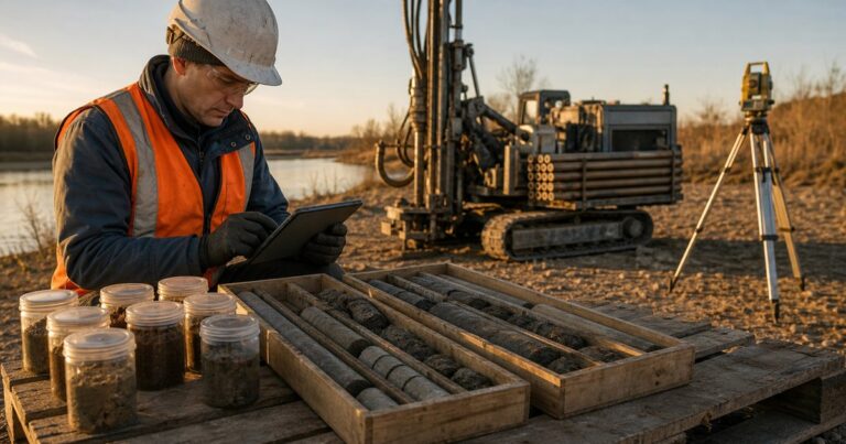
An HDD geotechnical investigation (horizontal directional drilling geotechnical investigation) is the owner’s data set for a crossing: borehole and test-pit logs, in-situ and laboratory test results, and the interpreted profile that turns them into design input. This guide sets out which boreholes and test pits to drill and how far apart and how deep, which in-situ and laboratory tests to run, and the deliverables to accept at handover. Every spacing, depth and test figure quoted here is an input to project-specific design and must be confirmed by a competent engineer for the actual crossing.
What Should an HDD Geotechnical Investigation Cover?
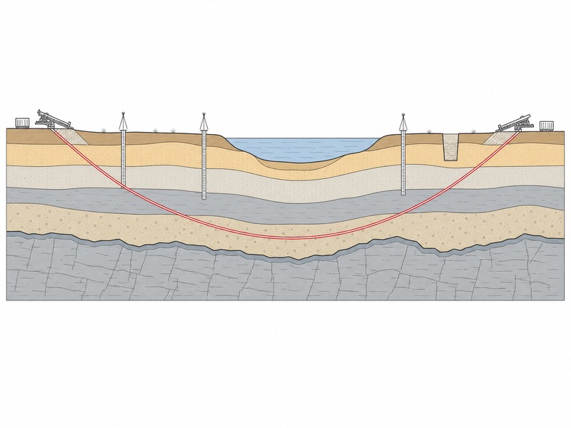
An HDD geotechnical investigation has to describe the ground along the whole alignment, not only at the two ends, because every stratum between entry and exit is part of the design problem.
- Along-alignment coverage: a profile that follows the bore from the entry area, under the crossed feature, to the exit area.
- Depth below the bore: enough investigation under the deepest point of the drive to prove the material the reamed hole will sit in.
- Properties, not descriptions alone: strength, density, stiffness, permeability, groundwater head and corrosivity.
- An interpreted profile: a design line with rock head and unit boundaries, not unrelated logs.
The NASTT HDD Good Practices Guidelines and ASCE Manual of Practice 108 call for a ground investigation report from a geologist or engineer with HDD experience, covering boreholes, penetration tests and a characterisation profile along the alignment, and the edition cited in the specification should be confirmed as the one currently in force.
This page covers the owner’s data set rather than the measurement method. Measuring soil stability before a trenchless project is the subject of a separate guide; here the question is which investigation data to buy, how much is enough, and what to accept at handover. General material on soil and rock types gives useful first orientation, but it does not say what the bore meets at a given station.
Where Should Boreholes and Test Pits Be Sited, and How Deep Do They Go?
Borehole spacing and depth are decided case by case, from how quickly the ground changes and the cost of being wrong about it. Published ground investigation guidance sets boring and test pit spacing from the desktop study of the local geology and the data already available, so the interval is a judgement rather than a fixed number.
- Prove both ends and the feature: at least one investigation point in each working area, plus points beneath the crossed feature. Long crossings and variable ground need intermediate points, which is where borehole spacing is decided case by case.
- Offset the holes from the bore: where they can be moved, holes should not sit on the alignment. Published highway practice for directional drilling offsets exploration holes by at least two pipe diameters or 3 m (10 ft), whichever is greater. The offset keeps the hole from becoming a weakness or a fluid path.
- Depth follows the drive: boreholes should reach below the deepest point of the proposed bore, and below the reamed envelope, far enough to confirm that no softer or harder stratum sits immediately beneath. Under a watercourse the controlling depth is the scour assessment, not the present bed level.
Two geometric figures set the width of the zone that must be characterised: the reamed hole is typically 1.2 to 1.5 × the product pipe outside diameter, so the zone needing characterisation is wider than the pipe; and the cover window, commonly specified between 0.9 and 1.5 m, is the barrier against fluid reaching the surface.
In our design reviews, the depth that decides a crossing is rarely the total depth of the hole; it is whether the investigation proved what lies immediately below the bore where the profile is shallowest.
Which In-Situ Tests Should an HDD Geotechnical Investigation Include?
The in-situ test schedule for an HDD geotechnical investigation follows the design decisions rather than a fixed menu, because the value comes from matching each method to the decision it supports.
- Standard penetration tests give penetration resistance and a disturbed sample, enough to classify the ground and judge drillability in granular deposits.
- Cone penetration tests give a near-continuous resistance record, showing boundaries between boreholes that a log alone can only infer.
- Rock coring recovers the rock mass itself, with core recovery and rock quality designation (the percentage of core in intact pieces longer than 100 mm), describing fracture spacing and quality.
- Pressuremeter testing measures in-situ deformation and stiffness, supporting the settlement assessment where the bore passes beneath infrastructure.
- Permeability and packer tests measure how readily fluid moves through a zone, the direct input to drilling fluid loss and frac-out (an inadvertent return to the surface) risk where cover is thin or rock is fractured.
- Groundwater and artesian head measurement, by installed wells rather than a strike noted while drilling, establishes standing level, seasonal range and any confined pressure that drives inflow or dewatering.
- Soil resistivity and aggressivity testing, commonly by the Wenner four-electrode method, supports coating selection and cathodic protection design.
Each in-situ method answers a different design question, so the schedule is a set of complementary tests rather than a menu of alternatives. On crossings we have supported, the recurring gap has not been missing boreholes but a missing permeability test in a shallow-cover granular zone, which is why rock coring alone is not enough.
The table below is decision-led: each method is mapped to the design output it supports and to the length of alignment where it matters.
| Test or method | What it tells the HDD designer | Where it is needed along the alignment |
|---|---|---|
| Standard penetration test | Soil density, strength class, drillability, sample | Entry and exit areas, granular sections |
| Cone penetration test | Continuous stratigraphy, weak zones, unit boundaries | Soft or layered ground, watercourse bed |
| Rock coring with rock quality designation | Rock mass quality, fracture spacing, reaming rate, tool wear | Rock head and rock sections |
| Pressuremeter test | In-situ stiffness for the settlement assessment | Beneath roads, rail and structures |
| Packer or permeability test | Hydraulic conductivity, loss of returns potential | Shallow cover, fractured rock |
| Groundwater and artesian head | Standing level, inflow, dewatering demand | Working areas, watercourse banks |
| Soil resistivity and aggressivity | Coating selection, cathodic protection demand | Buried sections and both working areas |
| Test pits | Shallow soils, cover confirmation, utility verification | Entry and exit areas, approach trenches |
The table is a scope aid, not a specification. Which tests an HDD geotechnical investigation needs depends on the ground, the geometry and the neighbouring assets, and the final schedule must be confirmed by a competent engineer for the actual crossing.
What Laboratory Testing Should the Ground Investigation Report Include?
Laboratory testing should turn samples into the design values behind each decision: rock strength and durability, soil gradation and plasticity, and chemistry for coating and cathodic protection.
- Gradation: particle size distribution drives cuttings transport, fluid properties and reaming behaviour, and it feeds the settlement assessment.
- Plasticity: liquid and plastic limits show how clay reacts when wetted, including swelling that slows reaming.
- Uniaxial compressive strength: the primary measure of rock strength. Published classification bands run on a uniaxial compressive strength basis from very weak, below roughly 5 MPa, to strong at about 50 to 100 MPa and above; they are typical published rock-strength bands rather than one named specification, so confirm the classification used for the project.
- Point load index: a cheaper test run on many core pieces and correlated to compressive strength, useful where recovery is limited.
- Abrasion testing: Los Angeles abrasion and the Cerchar abrasivity index estimate cutter and reamer wear.
- Slake durability: shows how weak rock breaks down under wetting and drying, affecting hole stability and cuttings handling.
- Chemistry: pH, chloride, sulfate and laboratory resistivity complete the aggressivity picture for coating and cathodic protection.
Our field teams record which properties were actually used, and it is almost always strength, abrasivity, permeability and chemistry. Gradation and plasticity matter most in soil sections, where they explain fluid behaviour and reaming torque rather than pipe stress.
Which Deliverables Should the Owner Demand From a Ground Investigation Report?
A ground investigation report should deliver both the factual record and the interpretation that turns it into design input, and the owner should be able to tell which is which.
The table below lists the investigation deliverables an owner should require and the defects that justify rejecting each; it is a checklist for scope and review, not a substitute for project-specific engineering.
| Deliverable | Why it matters to the crossing | What to reject |
|---|---|---|
| Borehole and test pit logs | Factual record at the level the bore will use | No survey level, no datum, rock head described but not measured |
| Characterisation profile along the alignment | One design line with units and rock head | A profile that stops at the crossing limits or bridges long gaps |
| Drillability and reaming assessment | Tooling, reaming stages, penetration rate, rig demand | Rock descriptions with no link to how the bore will be cut |
| Risk assessment for drilling fluid loss and frac-out | Where returns can be lost and how the site responds | Risk in general terms, with no permeability testing behind it |
| Settlement and ground movement assessment | Structures, roads, rail and services above the bore | No in-situ stiffness data and no movement limits |
| Dewatering and groundwater control basis | Sizes pit dewatering and treatment before works start | A single drilling water level used as the design level |
| Corrosivity summary for coating and cathodic protection | Coating selection and cathodic protection demand | Resistivity with no method, depth or spread configuration |
Reject is used here at the level of completeness: a deliverable is rejected when it is absent, undated, or unsupported by testing.
We have seen handovers in which the factual report was thorough and the interpretation was absent, so the design team rebuilt the profile by hand. Requiring both documents, with an assumption register between them, is the fastest test of what an HDD geotechnical investigation has actually delivered.
How Much Investigation Is Enough to Cover the Crossing Risk?
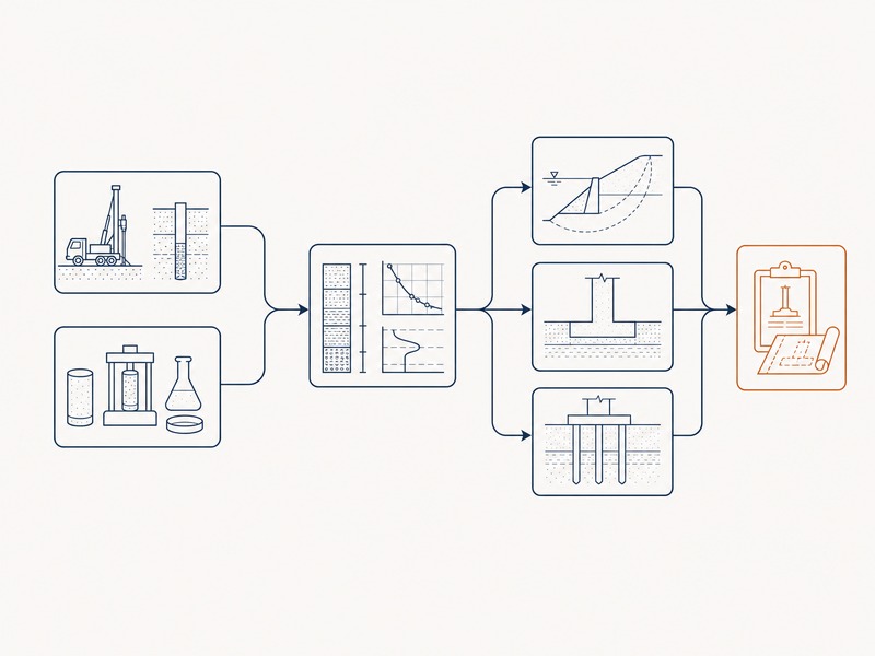
Investigation should be sized to the risk the crossing carries: it is a small share of the cost of a directional crossing, while the events it prevents – a lost-returns shutdown, a stalled reamer or a failed pull – are among the largest.
A proportionate scope is usually built in four tiers, in the sequence we use when we review a proposed investigation:
- Tier 1, desktop study: published geology, existing boreholes, utility records and imagery decide where intrusive work is worth placing.
- Tier 2, targeted holes: investigation points at entry, exit and beneath the crossed feature, deep enough to prove the material below the bore.
- Tier 3, continuity: cone soundings or geophysics between the holes where the profile is variable or access is restricted, so gaps are measured rather than assumed.
- Tier 4, decision-driven testing: permeability, stiffness, strength and chemistry added only where a design decision depends on them.
The investigation must be complete before the bore plan is fixed, because the profile, not an assumption, sets the depth and the bend radius the design can use.
Every spacing, depth and test figure in this guide is an input to project-specific design. None of it substitutes for calculation, and the scope must be confirmed by a competent engineer against the actual ground, geometry and neighbouring assets. Where the investigation hands over, the feasibility study and the bore plan in this series carry the data forward.
Frequently Asked Questions
What is an HDD geotechnical investigation?
An HDD geotechnical investigation is the set of boreholes, test pits, in-situ tests, laboratory tests and reporting that describes the ground a directional bore will pass through. Its purpose is to replace design assumptions with measured values for strength, permeability, groundwater and corrosivity.
How far apart should boreholes be on an HDD crossing?
Borehole spacing is set for each crossing from the desktop study, the variability of the geology and the consequence of an unexpected zone, with at least one investigation point in each working area and points beneath the crossed feature. Ground that changes quickly needs closer spacing.
How deep should boreholes go for a horizontal directional drilling crossing?
Deep enough to pass below the deepest point of the proposed bore by enough to prove that no weaker or harder stratum sits immediately beneath it, and below the reamed envelope rather than only below the pipe centreline. Under a watercourse the required depth follows the scour assessment.
Why does the investigation have to test for drilling fluid loss?
Loss of returns and frac-out are ground-controlled events that the investigation has to test for, because drilling fluid can escape to the surface or into a watercourse where cover is thin or rock is fractured. Permeability tests and a described cover thickness show where drilling fluid can escape to the surface or into a watercourse, which lets containment and response measures be priced before construction rather than improvised during it.
What laboratory testing matters most in rock?
The laboratory tests that matter most in rock are uniaxial compressive strength, point load index, abrasion and slake durability, supported by core recovery and rock quality designation. Strength and abrasivity drive penetration rate and cutter wear, while durability and fracture spacing govern post-reaming hole behaviour.
What should an owner reject in a ground investigation report?
Reject logs without survey levels or a stated datum, conclusions that never reach a profile along the alignment, and reports that give a single permeability or strength value with no testing basis. A factual log set without interpretation leaves the designer to guess.
Key Takeaways
- An HDD geotechnical investigation is specified by the owner and must describe the ground along the whole alignment, not just at the ends.
- Borehole spacing and depth follow the crossing depth, the reamed envelope and the variability of the ground, so both are site-dependent.
- Match each in-situ test to the decision it supports, and add permeability testing wherever cover is thin or rock is fractured.
- Laboratory testing should cover gradation, plasticity, rock strength, abrasion, durability and chemistry.
- Demand the interpreted profile and the assessments derived from it, not only the factual logs.
- Scope the investigation in tiers against crossing risk, and confirm every figure through project-specific engineering.
How JSW Supports HDD Geotechnical Investigation and Design
JSW is a pipeline engineering and construction company that plans and builds trenchless crossings with its own engineering team, crews and equipment. Our teams cover HDD crossing services, trenchless technologies and microtunneling construction. Around the investigation, we also deliver pipeline installation services and pipeline inspection service, so the ground data an investigation defines is the same data our installation and inspection crews work to on site.
Because the group that reviews the investigation also drills the crossing, our scope notes name which data the design will consume and which gaps become construction risk. We work from the interpreted profile rather than assumed strata.
- Integrated delivery: investigation review, bore plan, stress checks, pipe string fabrication and pullback inside one scope, removing the interface between designer and constructor.
- Auditable engineering: the log set, the interpreted profile and the assumption register between them are documented, so each design input traces back to its source.
- Risk-explicit pricing: contingencies and the conditions that trigger them are stated rather than absorbed into a single lump sum.
- Crossing experience: watercourse, road and rail crossings and congested urban corridors, with permitting, fluid management and restoration inside the scope.
Not sure whether your investigation covers enough ground? Send your borehole logs, characterisation profile, test results and your investigation scope or specification for a free technical review. Our engineers respond with the data gaps we see, the tests worth adding, and a budget range.





































 English
  Arabic
  Russian
  Spanish
  French
  Vietnamese
  Polish
  Thai
Thai  Indonesian
  Turkish
  Portuguese