
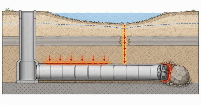
Most microtunneling problems are symptoms rather than causes. In published forensic cases the real faults were a water model that missed an artesian aquifer, a shaft that breached the clay layer sealing it, and a design grade with no tolerance for error.
Microtunneling problems are rarely caused by the machine; the published record points at the investigation. This page works through the failure modes that actually stop drives. The evidence base is a NASTT forensic paper on a failed project in coastal California, a 2014 paper on a mixed face drive under the Schuylkill River, and contractor accounts from Jacko Lake, Paradise Cut, Tampa and New York. Each mode is paired with the early warning to watch and the evidence to ask for before pricing.
What Kinds of Microtunneling Problems Actually Happen?
A machine fault is a maintenance issue; a missing water model is a design issue that turns an ordinary drive into a claim. The seven failure modes below are grouped by where the leverage actually sits: the geotechnical investigation.
| Failure mode | Mechanism | Early warning | Mitigation |
|---|---|---|---|
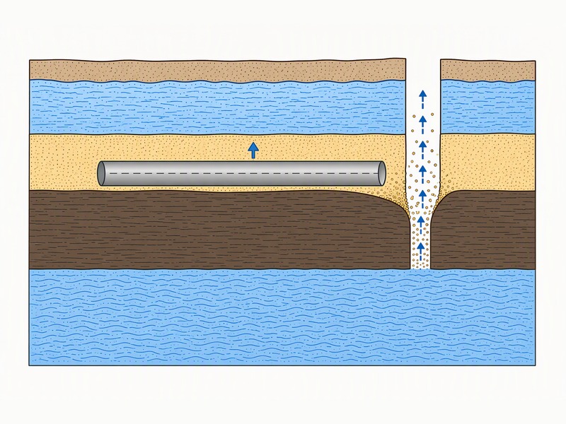
| Loss of line and grade | Buoyant pipe rises into a void above it | Pipe rising near the shaft after a survey that passed | Seal the shafts; deepen below the aquitard |
| Pipe breakage | Compressive load exceeds the pipe rating | Jacking force climbing toward the calculated limit | Reduce friction; add intermediate jacking capacity |
| Artesian pressure and water inflow | Upward seepage through a breached aquitard | Piezometer trend across seasons | Grout the shafts; or deepen below the aquitard |
| Mixed face and rock | Tool wear and steering deflection at variable strength | Falling advance rate; rising force and torque | Rock tooling with cutter access designed in |
| Buried obstructions | Debris, wood, fill or boulders at the face | Advance rate stalls; force spikes | Mixed ground cutterhead; an obstruction policy |
| Stoppages and friction | An idle pipe string builds skin friction | Force does not return to trend after a restart | Keep tunneling; change the mud design |
| Ground settlement | Overcut and face pressure imbalance | Monitoring trend, not a single reading | Reduce the overcut; match pressure to the water table |
Failure 1: Losing Line and Grade to Pipe Flotation
The clearest documented failure is a forensic case published through NASTT: eight drives totalling 3,445 ft at a very flat 0.1 percent grade through a coastal wetland in California. The parties are not named in the paper, and the case is reported here as published.
The mechanism was not what the parties first assumed. Pipes installed within one inch of line and grade were found on re-survey with humps of five and four inches out of tolerance. The cause lay in three aquifers separated by clay layers. The alignment ran just below the aquitard between a shallow perched aquifer and a seasonally pressurized primary aquifer, and the shafts had breached that aquitard without sealing it. When the primary aquifer turned artesian, upward seepage piped sandy soil out from above the buoyant pipe.
- Confirming evidence: the one drive built inside clay did not move, because clay is not susceptible to piping.
- Missed signal: the lift station contract had already met pressurized water and paid to depressurize it. None of that reached the microtunneling contract.
- Design gap: ten borings along the alignment, with water within 10 ft of the surface, but no piezometers.
Bottom line: a survey that passes on installation day confirms the line and grade achieved; it does not confirm the pipeline stayed there.
Failure 2: Pipe Breakage Under Jacking Load
A pipe breaks when compressive load at a joint exceeds what it was rated to carry, and that load is cumulative: every meter of pipe in contact with the ground adds friction the jacking frame must overcome. In the same forensic case, a 444 ft drive ended when the pipe broke at 460 ft while the contractor was pushing within 50 tons of the pipe’s safe jacking force, calculated with a safety factor of 2.5. Water flooded the machine and the shaft, and the drive finished by open cut.
What protects a drive is a thrust limit calculated before launch and monitored throughout. Friction in pipe jacking typically falls between 0.5 and 2.5 tonnes per square meter of external circumferential area, and lubrication can reduce that to as little as 0.1 tonnes.
Failure 3: Groundwater and Artesian Pressure
Groundwater is the most common root cause among the published microtunneling problems, because it is measured less carefully than soil. A borehole profile can name every stratum correctly and still mislead, because pressure is a dimension one borehole does not capture.
The Schuylkill River drive in Reading, Pennsylvania, published by Bradshaw Construction, shows the theme from another angle. River water followed the overcut annulus into the cutterhead even with a thick polymer-bentonite lubricant, and testing proved the water was not coming through the rock. The only workable fix was to grout the annulus before a cutter change.
- Investigation: piezometer readings across the seasons, not a single strike depth.
- Specification: where artesian conditions are possible, require a grouting program that seals the shafts rather than relying on a watertight lining.
- Alternative: deepen the alignment below the aquitard so the critical gradient is higher.
Failure 4: Mixed Face, Rock and Cutter Wear
Mixed face is where soft ground and rock appear in the same heading, and it defeats tooling that is right for either one alone. The Schuylkill drive is the documented example: 436 ft of 60 inch casing with as little as 5 ft of cover under the river. That drive began in gravel over fractured dolomitic rock and ended in full face rock peaking at 34,300 psi.
The geotechnical investigation under-called the ground: twelve borings along a 436 ft alignment still missed the top of rock by up to 12 ft. The specification contradicted the geology, requiring a machine able to crush 30,000 psi material while the report showed 34,300 psi. And the annulus was limited to 0.5 inch radially, which the author states is inappropriate in full face rock.
Mining averaged 10 ft through weathered rock, 14 ft through the mixed face and 12 ft in full face rock. The drive ended with a cutter chamber intervention that found the number two disc cutter flat-spotted from a bearing failure.
Failure 5: Buried Obstructions and Debris
Microtunneling problems from obstructions show the widest gap between the desktop study and the face: what stops a drive was usually put there by people rather than geology.
- Paradise Cut, California: a 680 ft drive through sands and residuum met obstructions in the flood plain layers, including wood.
- New York City: a 116 ft drive of 66 inch casing through poor soil containing nails, lumber and historical fill.
- Tampa: jacking loads rose from about 24.5 tons to over 124 tons during a 754 ft drive, requiring continuous tunneling to prevent seizure, with constant adjustment of slurry flow and face pressure.
Failure 6: Stoppages and the Intermediate Jacking Station Trap
Stoppage is the most underrated of the microtunneling problems. When a drive stops, the pipe string stops moving through ground that is closing around it, so the friction the machine must overcome on restart is higher. On the Jacko Lake drive in British Columbia, which ran 1,173 m on a continuous horizontal radius, the contractor reported that stoppages exponentially increased skin friction. That forced a change to the mud design and the use of an intermediate jacking station.
A force reading that does not return to trend after a restart is a warning rather than noise, and where friction is already steep the location of an intermediate jacking station must come from the calculated profile.
Failure 7: Ground Settlement and Shallow Cover
Our field teams record ground settlement as a consequence of soil loss and stress release, not an operator error. Settlement is bounded by two variables: the annular gap cut around the casing and the face support pressure at the cutterhead.
The gap is typically 13 to 38 mm, and a 35 mm overcut may create settlement. For road and rail crossings the overcut is reduced to hold subsidence to about 10 mm. On the Schuylkill drive, cover under the river was as little as 5 ft. Drilling fluid reached the surface where shallow cover met a gravel over rock mixed face.
The forensic case recommends the two-diameter cover rule. The specification set a minimum of two diameters or six feet, and the channel crossing had only 2.6 ft of cover over the crown.
What Do These Failures Have in Common?
Four root causes account for almost all of the microtunneling problems above, and none is a machine limit. On drives we have supported, the water model is the item nobody owns.
- An incomplete groundwater model. No piezometers, a single season of data, or a pressure regime known on a neighboring contract and never passed across.
- A geotechnical investigation read as fact rather than expectation. The Schuylkill drive had a boring roughly every 40 ft and still found rock 12 ft high.
- A design with no tolerance for construction reality. A grade of 0.1 percent leaves nothing for the ground to absorb.
- Information held in separate contracts.
Scope: the cases above describe specific published projects under the conditions their authors reported. Confirm each point against the baseline report and alignment drawings before pricing.
What Should a Pre-Bid Risk Screening Checklist Ask?
We have seen screening used to find the questions the data cannot answer.
| Item | Question to answer | Evidence required |
|---|---|---|
| Aquifer pressure | Is any aquifer artesian, and how does that vary by season? | Piezometer records, not a single strike depth |
| Shaft sealing | Can the shafts be sealed against artesian uplift? | A grouting program or a watertight lining design |
| Top of rock | How much higher than predicted could it be? | Stated uncertainty, or a geotechnical baseline report |
| Cover at crossings | Is cover at least two diameters throughout? | The alignment drawing checked against the rule |
| Friction profile | Where does cumulative friction reach the thrust limit? | A calculated profile with station locations marked |
Key Takeaways
- Most microtunneling problems start in the investigation, not at the face: an incomplete model of groundwater is the most common root cause.
- Jacking force is cumulative along the pipe string, and a pipe has broken within 50 tons of its rated limit.
- Mixed face defeats tooling for either ground alone, and cutter access for tool changes is a design requirement.
- Stoppages raise skin friction, and the mud design rather than an extra jacking station is the real fix.
- Artesian pressure, not soil type, is what the published failures turned on; a boring log alone rarely shows it.
Frequently Asked Questions
What is the most common cause of microtunneling problems?
Information that never reached the design. In a published forensic case, a lift station contract on the same site had already met pressurized water and the owner paid to depressurize it, none of which reached the microtunneling contract.
Can a jacked pipe float after it has been installed?
Yes, and it has happened. Drives surveyed within one inch of line and grade were later found with humps of five and four inches out of tolerance, after upward seepage through a breached clay aquitard piped sandy soil out from above a buoyant pipe.
What jacking force will break a pipe?
Whatever the pipe is not rated for. In a published forensic case the pipe broke while the contractor was pushing within fifty tons of the safe limit, calculated with a safety factor of 2.5.
When is an intermediate jacking station needed?
When accumulated friction consumes the available thrust before the machine reaches the reception shaft. On one Canadian drive the contractor reported that stoppages exponentially increased skin friction, forcing a change to the mud design and the use of an intermediate jacking station.
How much ground settlement does microtunneling cause?
Tolerable amounts if overcut and face pressure are managed. The annular gap is typically 13 to 38 mm, and a 35 mm overcut may create ground settlement. For road and rail crossings the overcut is reduced to hold subsidence to about 10 mm.
What should a geotechnical investigation answer before a bid?
Aquifer pressures and their seasonal range; the elevation of the top of rock; the expected length of any mixed face; the size of any obstructions; and the presence of fill or debris, plus what the investigation did not resolve.
How JSW Supports Projects Like These
JSW is a pipeline engineering and construction company that executes trenchless crossings with its own crews and equipment. Our scope covers microtunneling construction, trenchless technologies, horizontal directional drilling services, pipeline installation services and pipeline repair services.
Most microtunneling problems we price arrive as a scope with an optimistic ground model. We screen the geotechnical investigation before the machine: aquifer pressure, aquitard continuity, top of rock uncertainty and obstruction policy come first, and where the data cannot answer them we price the risk explicitly.
- Investigation-first review: the report, alignment and shaft design are checked against each other before a machine is selected.
- Monitored drives: jacking force, guidance deviation, lubrication volume and advance rate logged against pre-calculated limits.
- Explicit risk allocation: obstructions, mixed face and water control priced as identified risks.
- Compliance: ISO 9001:2015, ISO 14001:2015 and ISO 45001:2018 certified management systems.
Concerned about the ground model behind your drive? Send the geotechnical report, alignment and shaft drawings for a free technical review. Our engineers respond with a scoped risk view and budget range.
Sources and Standards
The case material on this page is drawn from published sources. The forensic case in coastal California comes from a NASTT 2014 No-Dig paper presenting a forensic analysis of a failed microtunneling project, in which the owner, project and designer are not named, and is documented as paper MM-T5-02, NASTT 2014 No-Dig Show, Orlando.
Mixed face and settlement detail comes from a 2014 paper by Bradshaw Construction on a mixed face and mixed reach hard rock drive under the Schuylkill River in Reading, Pennsylvania. Contractor accounts come from industry job logs and project publications covering Jacko Lake in British Columbia, Paradise Cut in California, Tampa in Florida and the East Side Coastal Resiliency works in New York. Those cases were reported between 2014 and 2026.
Standards referenced in the text are ASCE/CI 36-15, Pipe Jacking Association guidance on jacking lengths, friction, overcut and shaft design (the friction and overcut ranges quoted above come from that guidance), NASTT good practice material, and EN 12889. No external link or citation marker is used.





































 English
  Arabic
  Russian
  Spanish
  French
  Vietnamese
  Polish
  Thai
Thai  Indonesian
  Turkish
  Portuguese