
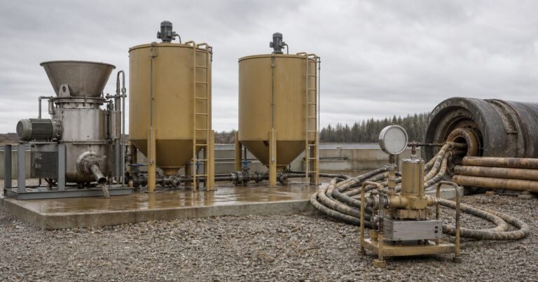
Bentonite lubrication (also called annular or pipe-jacking lubrication) is the practice of filling the annular gap between the pipe string and the ground with a bentonite-based suspension so that jacking friction stays low enough to reach the reception shaft. It does two jobs at once: it lubricates the pipe-ground interface, and it supports the surrounding soil so the annulus does not close onto the pipe. Here the suspension injected into the annulus is the lubricant; the circulating fluid that supports and clears the face is the slurry, and the two are specified separately.
This guide is for owners specifying the works, contractors preparing a bid, and the engineers and supervisors who run the drive. It covers the practical decisions in order: how the annular gap and overcut are dimensioned, why the suspension behaves differently in silt and in gravel, what the friction numbers are worth and where they come from, how the suspension is mixed and swollen, where it is injected along the drive, why the entry seal decides whether any of it works, how lubrication interacts with face support, and what to record on every push so a failing film is detected before the jacking force rises.
What Bentonite Lubrication Actually Does
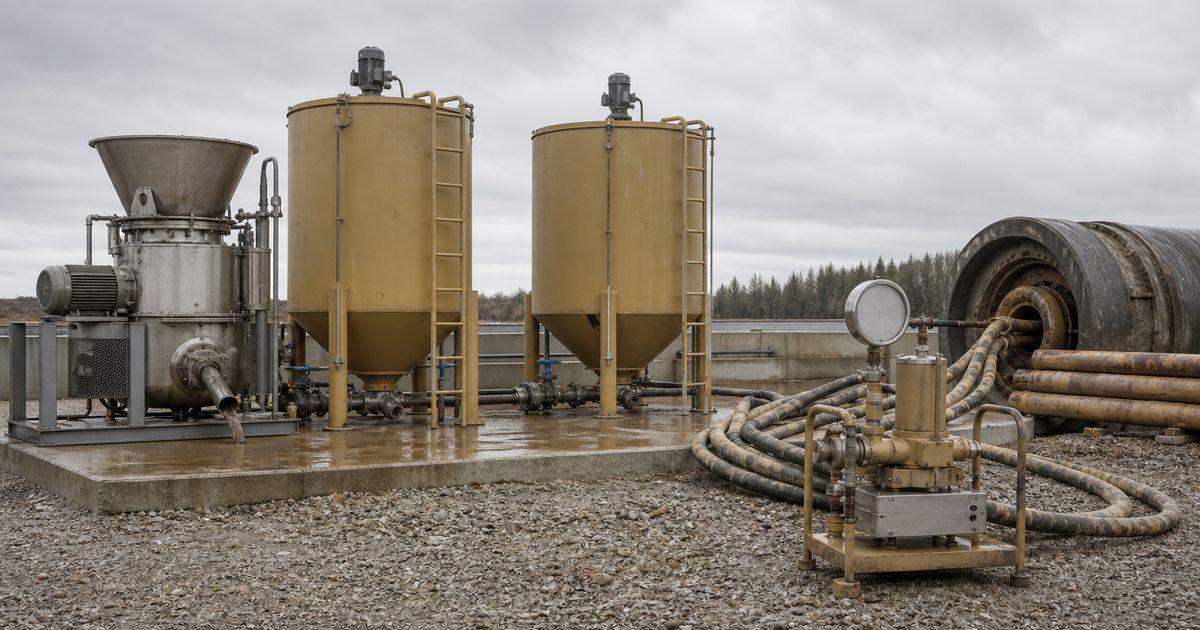
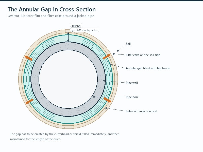
The annulus created by the cutterhead or shield has to be filled with bentonite immediately, because bentonite lubrication reduces skin friction both as a lubricating film and by supporting the surrounding soil.
Bentonite lubrication is specified as a fluid problem rather than a pumping problem. The pump, the injection points and the control regime only deliver the fluid; whether the drive benefits depends on whether the suspension’s properties match the ground it is injected into.
Dimensioning the Annular Gap: Overcut Is a Design Decision
The annular gap, also called the annulus, is created by the overcut, and overcut is a design decision. The larger the outside diameter, the larger the overcut.
Overcut is set by three inputs in order: the design rule for the pipe diameter (about 5 mm to 50 mm by radius, small end for roughly 300 mm OD and large end for about 3,000 mm OD), the specification cap where one applies (30 mm or 2% of pipe outside diameter, whichever is smaller), and the steering room the alignment actually needs.
Project-specific boundary conditions always enter the decision: cover depth, permissible settlement, pipe length, bends, and the deviations the control system will inevitably produce. Some specifications impose a firm cap – a published water-industry specification requires the overcut of the tunneling shield not to exceed 30 mm or 2% of the pipe outside diameter, whichever is smaller.
Applies to rigid jacking pipe driven in soil on a controlled line and grade. Not applicable where the drive is in rock, or where the alignment needs a curvature the pipe string cannot follow: there the annulus is set from the drive design and confirmed against the actual ground and pipe.
Whether the annulus is cut by the machine itself – usual for slurry machines – or by a shield with an internal cutterhead is a project decision, and the internal cutterhead alternative is worth discussing where material is strongly rolling. An overcut that is too small can stop the jacking altogether or damage individual pipes: because every controlled drive deviates from the nominal axis, a generous annulus gives the string room to follow the machine’s steering without being forced through the cavity. In rock drives the damage pattern is characteristic, with radial cracks forming approximately in the middle of a pipe.
Bottom line: the gap has to be wide enough for the deviations the control system will actually produce, not just for the nominal pipe outside diameter. A bentonite lubrication system can only work with a gap to fill, which is why the overcut is settled before the fluid specification.
Why Lubrication Works: Ground Behavior and the Friction Numbers
The same bentonite suspension supports the annulus by two different mechanisms depending on the pore size of the ground, and knowing which mechanism is doing the work determines how the fluid should be specified.
- Small pores, thin filter cake. In fine soils such as silt, the supporting effect can be produced by a relatively thin outer filter cake, because the ground itself does not let the suspension penetrate far.
- Large pores, stagnation. Where pores are large enough for the suspension to enter the surrounding soil – coarse sand or gravel – the required supporting effect has to be achieved by stagnation. The suspension is then mixed and prepared specifically so that its properties allow it to stagnate in the corresponding pore size.
- The controlling property. For stagnation, the static yield point is the decisive reference value, measured in accordance with the German DWA/DIN framework.
- The volume consequence. Penetration of suspension into the pores consumes additional material to stabilize the annulus, so a gravel drive needs both a different fluid and a larger quantity of it.
In our site reviews, the single most common specification gap is a lubrication system sized for the pipe diameter and the drive length, with the suspension specified only as “bentonite”. The suspension should be specified against a measured yield point matched to the ground’s pore size; that yield point is a project-specific input confirmed by the suspension supplier and a competent engineer for the actual ground.
Lubrication is justified by the size of the numbers it changes: published empirical pipe-jacking guidance puts frictional forces at 0.5 to 2.5 tonnes per square meter of external circumferential area, and reports that proper lubricant injection can reduce them to as little as 0.1 tonnes per square meter.
| Condition | Reported skin friction | Source framing |
|---|---|---|
| No effective lubrication | 0.5 to 2.5 tonnes per square meter of external circumferential area | Published empirical pipe jacking guidance |
| Lubricant injection applied properly | As little as 0.1 tonnes per square meter | Same published guidance |
| Fully automatic lubrication operated correctly | Below about 1 kN/m² | Operational experience reported in the technical literature |
| Lubricating film partially lost or other friction problems | Far more than 10 kN/m², exceptionally up to about 100 kN/m² | Same reported experience |
Unit note: 1 tonne per square meter is approximately 10 kN/m², so the 0.5 to 2.5 t/m² range corresponds to roughly 5 to 25 kN/m²; all figures are typical published industry values used for planning, without a specific project source.
The difference between a drive that runs with the main jacking station alone and one that jams is the loss of the film rather than a gradual deterioration in the bentonite, which is why the film is judged by its continuity along the drive.
Bentonite Mixing and Swelling: Water Quality, Time and Yield
Bentonite mixing is a process rather than a purchase: a suspension only works if it has been prepared properly. Mixing water, mixing time, mixing efficiency and swelling time all have a large influence on yield and on the suspension’s stability against impurities in the ground. Bentonite mixing is also the point at which the batch record is created, because the yield actually measured on site is the only evidence that the fluid meets the specified pore-size requirement.
- Mixing water. It should have low hardness and a pH of about 8 to 10. Hard or acidic water reduces the yield the specification assumes.
- Swelling time. The suspension has to be given time to swell before it is pumped. An unmatured suspension is not a weak lubricant; in swelling clay it is actively harmful, because introducing suspension that has not yet swollen can cause the soil to swell, raising skin friction and potentially jamming the string.
- Long residence time. Lubricated bentonite stays in the annulus for a long time, so the suspension must not release water to the surrounding soil over the life of the drive.
- Quantity. How much bentonite a pipe-jacking drive needs is the sum of three terms – the volume that fills the annular gap, the penetration loss into the ground, and the maintenance dose along the pipe string – reconciled against the tank volume actually provided on site.
Injection Strategy: The First Injection and the Maintenance Injections
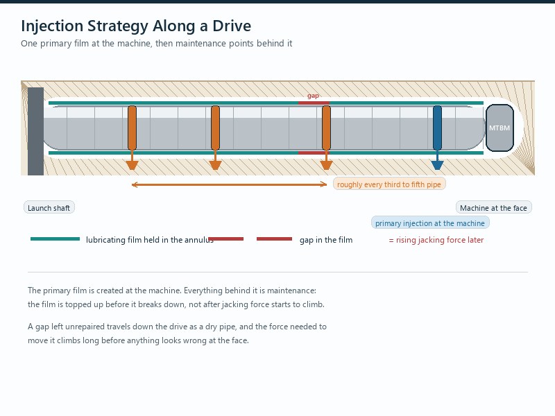
Automatic lubrication systems typically control the initial injection directly at the machine, so that the required quantity of bentonite is injected at the first injection point. This is an important prerequisite, because the primary film has to be complete before the pipe string follows it.
Along the pipes that follow the machine, the built-up bentonite film only has to be maintained continuously rather than allowed to break. Common practice is subsequent injection in roughly every third to fifth pipe, with the quantity adjusted to advance speed and geology and delivered at the appropriate points around the pipe string.
Volume-controlled systems with a real-time display of grouting quantities along the route make the film visible: an interrupted film appears immediately as a gap in the delivered volumes and can be corrected automatically at the next bentonite station. Injection operates either to a set volume or to a set pressure: a set-volume system reports the shortfall when the annulus takes more fluid, a set-pressure system masks it.
The Entry Seal and the Face Support Interaction
The entry seal is what keeps bentonite in the annulus: where the seal is absent or leaks, groundwater flushes the suspension out of the gap before the next injection point, so a functional start-up seal is an elementary prerequisite for annulus lubrication. A seal that does not hold makes bentonite lubrication impossible: check and repair the entry seal before adjusting the injection regime. In our experience the entry seal is one of the cheapest items on the drive and one of the most consequential: when it leaks, the lubrication budget is being spent into the ground.
The face and the annulus share one hydraulic system – the working face, the plenum or mining chamber and the annulus – so what happens at the face shows up in the annulus. If the annulus is under-filled, part of the face slurry migrates into the gap, deposits fines there, and robs the annulus of its lubricating function.
A usable field diagnostic for annulus lubrication is the volume balance: in the slurry circuit, the quantity in the return line should always exceed the quantity in the feed line. An unexplained excess indicates that face suspension is migrating into the annulus, which in turn means the annulus is not properly filled with lubricant.
Seal readiness is also a pre-launch hold item, and it is covered in our guide to pre-project equipment testing and commissioning. For the friction side of the same drive, see our article on jacking frames, thrust rings and spacers.
What to Record Every Push, and How Lubrication Fails
Annular lubrication performance is measurable, and the record that changes first is jacking force per pipe advance; the readings below confirm what it is telling you. Measuring the film along the drive separates a planned maintenance injection from an emergency. In practice, bentonite lubrication is judged by whether the film is continuous along the drive, not by whether fluid was pumped into it.
| Parameter | Instrument or source | What a change indicates |
|---|---|---|
| Volume injected per station | Volume-controlled lubrication system | A gap in delivered volume shows the primary film has broken and the station did not cover it |
| Injection pressure | Injection pump pressure gauge | Lower than expected may mean the annulus is taking fluid, or that the seal is leaking |
| Jacking force | Calibrated gauges on the jacking frame and at each intermediate jacking station | Rising force per pipe advance is the earliest reliable sign of rising skin friction |
| Face and annular pressure | Face pressure gauges and annular pressure readings | Divergence suggests migration between the annulus and the face circuit |
| Return versus feed volume | Slurry flow meters | Return line quantity should exceed feed; an unexplained excess means suspension is escaping into the annulus |
| Suspension properties | Density and static yield point testing at the bentonite mixing plant | Confirms the fluid being injected still matches the specified properties for the ground |
| Symptom | Mechanism | Remedy |
|---|---|---|
| Jacking force rising steadily along the drive | Primary film never formed, or lubrication dose too low | Restore initial injection quantity, increase maintenance dose, confirm suspension properties |
| Injection volumes not matching set volumes | Annulus taking more fluid than specified, or a leaking seal | Inspect the entry seal, review yield point and review injection pressure setting |
| Lubricant found in the shaft behind the seal | Entry seal failure | Repair or replace the seal first, then resume lubrication |
| Sudden friction increase at a geological boundary | Water flow in the annulus flushing the suspension | Anticipate with pre-injection where the risk is known; review the drive plan |
| Pipe string binding in swelling clay | Unswollen or unmatured suspension causing the ground to swell | Extend swelling time and re-check water quality and pH before pumping |
| Fines accumulating in the annulus | Face suspension migrating into an under-filled annulus | Restore annulus filling; monitor return versus feed volumes |
Key Takeaways
- Bentonite lubrication reduces skin friction both as a lubricating film and by supporting the surrounding soil; a suspension that does neither leaves the drive to the jacking frame alone.
- Radial overcut is usually between about 5 mm and 50 mm, and some specifications cap it at 30 mm or 2% of pipe outside diameter, whichever is smaller.
- Filter cake governs support in fine soils and stagnation governs it in coarse sand and gravel, which makes the static yield point the controlling fluid property.
- Published empirical friction ranges run from 0.5 to 2.5 tonnes per square meter, reducible to about 0.1 tonnes per square meter with proper injection; below about 1 kN/m² is achievable with fully automatic lubrication operated correctly.
- Mixing water should have low hardness and a pH of about 8 to 10, and the suspension must be fully swollen before use.
- A functional entry seal is a prerequisite for annulus lubrication, and an unexplained excess of return over feed volume is the classic sign that suspension is escaping into the gap.
Frequently Asked Questions
What does bentonite lubrication do in microtunneling?
A bentonite suspension fills the annular gap and reduces skin friction in two ways: as a lubricating film between the pipe and the ground, and by supporting the surrounding soil. Both effects matter, and a suspension that only lubricates without supporting the ground will lose the annulus as soon as groundwater moves through it.
How big should the annular gap be?
The annular gap is a design decision, not a by-product of the cutterhead. Overcut is usually between about 5 mm and 50 mm by radius, with small end for bores of roughly 300 mm outside diameter and large end for pipe jacking from about 3,000 mm outside diameter. Some specifications cap it at 30 mm or 2% of pipe outside diameter, whichever is smaller.
Why does filter cake matter in silt but stagnation in gravel?
Because the pore size of the ground decides how the suspension holds pressure. In fine soils a relatively thin outer filter cake is enough to give the supporting effect, while in coarse sand and gravel the suspension has to stagnate in the pores, which is why its static yield point becomes the controlling property.
What mixing water quality does bentonite need?
Low hardness and a pH of about 8 to 10. Mixing water quality, mixing time, mixing efficiency and swelling time all influence yield and stability, and an unmatured or insufficiently swollen suspension can do more harm than no lubrication at all, particularly in swelling clay.
Where should bentonite be injected along the drive?
The initial injection goes in at the machine, and the film is then maintained with injection at roughly every third to fifth pipe. Volume-controlled lubrication systems with a real-time display of grouting quantities detect a broken film immediately and can catch up the missed quantity at the next injection point.
What breaks bentonite lubrication in practice?
A leaking entry seal, uncontrolled water flow in the annulus, and a face pressure regime that pushes face suspension into the gap. A functional entry seal is a prerequisite for keeping the lubricant in place, and water flowing through fissures or water-bearing faults can flush the annulus out.
How JSW Supports Annulus Lubrication Design
JSW is a pipeline engineering and construction company that executes trenchless crossings with its own crews and equipment. Our scope covers microtunneling construction, trenchless technologies, HDD crossing services and pipeline installation services, and we design the annulus, the suspension and the injection regime as one system with the jacking plan rather than as a consumable purchase.
Because we hold the jacking forces and the lubrication records in the same file, a change in friction can be traced back to a station that did not deliver its volume or to a seal that started leaking.
- Annulus designed with the drive: overcut and gap set from diameter, alignment and permissible settlement rather than copied from a previous project.
- Suspension matched to pore size: fluid specified against a measured yield point for the ground, not against the word bentonite.
- Injection monitored, not assumed: per-station volumes, injection pressure and jacking force recorded so a broken film is detected early.
- Certified delivery: our trenchless work is delivered under ISO 9001:2015, ISO 14001:2015 and ISO 45001:2018 certified management systems.
Planning a long drive and not sure what annulus and lubrication capacity your ground needs? Send your pipe diameter, drive length, ground conditions and groundwater information for a free technical review. Our engineers respond with a scoped lubrication and annulus recommendation and an indicative budget range.





































 English
  Arabic
  Russian
  Spanish
  French
  Vietnamese
  Polish
  Thai
Thai  Indonesian
  Turkish
  Portuguese