
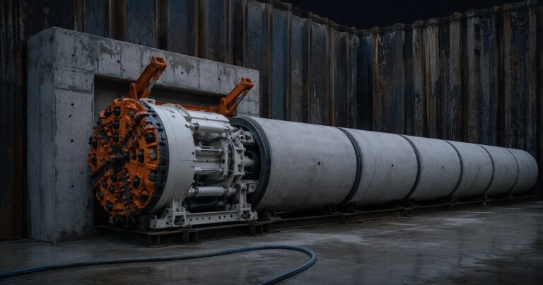
This working microtunneling glossary defines the microtunneling terms owners, engineers and bidders meet most often in specifications and tender documents. The entries run from the method and system names through machine and face, guidance, jacking and thrust, to shafts, pipe, settlement and commercial terms. Definitions follow the usage in ASCE/CI 36-15 and the Pipe Jacking Association guidance wherever those documents define the term, and say so where the figure quoted is an indicative planning value. Each term adds why it matters, and a table of typical values and units follows.
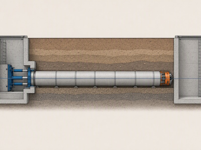
Which Terms Name the Method and the Systems?
These microtunneling terms name the method families.
MTBM
MTBM stands for microtunnel boring machine: the remotely operated, steerable machine that excavates the face and is pushed by the pipe string behind it. In bid reviews we check it first against the geotechnical report, because it fixes ground range, shaft size and guidance.
Slurry shield
A slurry shield is a closed-face MTBM that supports the face with pressurized bentonite slurry and removes spoil through a pipe. Its pressure balances groundwater and earth pressure, so it suits saturated, variable and rock ground. A slurry shield needs a surface separation plant, adding footprint and cost.
EPB machine
An earth pressure balance (EPB) machine supports the face with the excavated soil itself, conditioned with bentonite, water or polymer to form a plastic plug a screw conveyor can pressurize and extract. EPB machines suit cohesive soils and larger pipe jacks. Performance depends on the conditioning plan as much as the machine.
Auger machine
An auger machine is an open-face system: a rotating auger inside the casing removes spoil and gives little or no face support. In dry, stable ground an auger machine is economical; in unstable or water-bearing soil the drive needs a closed-face machine. Price auger machine drives only where the geotechnical report supports stable ground for the whole drive.
Pilot tube
A pilot tube system installs a line-and-grade reference first: small steel pilot tubes are jacked to the reception shaft, then cased augers follow and the product pipe is thrust through. A pilot tube system suits displaceable soils with shallow water tables or low permeability and is quoted accurate to about ±1 inch (25 mm) from grade. Drives are typically about 120 m or less, so it suits short crossings.
Guided boring
Guided boring is the wider name for the pilot-tube family, in which a guided reference bore controls line and grade before the product pipe is installed. The pilot string gives a measurable path rather than a calculated one, so errors are caught early. Guided boring is chosen where accuracy and shallow cover matter more than drive length.
How Do the Machine and Face Terms Differ?
The microtunneling terms in this group describe the machine and the face: face support, plenum, cutterhead, crushing head, overcut and annulus.
Face support
Face support is the pressure the machine applies to the face to stop ground and groundwater entering the bore. Face support can be pressurized slurry, conditioned earth or a controlled plenum, and separates a closed-face machine from an auger bore. Weak face support is a common cause of ground loss and settlement.
Cutterhead
The cutterhead is the rotating face that cuts the ground, with tooling from rippers and picks in soil to disc cutters in rock. The cutterhead design must match the ground, and wear limits long drives because nobody can enter the small bore to change tools. Cutterhead wear is a cost and program risk on rock and mixed faces.
Crushing head
A crushing head is a rotating or fixed arrangement of jaws and picks that reduces cobbles and boulders so they pass through the machine and slurry circuit. A crushing head protects the cutterhead and the pipe from oversized material.
Overcut
Overcut is the small annular gap cut ahead of the machine so the pipe can be steered and friction controlled. PJA guidance gives the typical overcut range and the settlement figures in Table 2. Overcut is the settlement-versus-steerability trade-off.
Annulus
The annulus is the ring-shaped gap between the jacked pipe and the surrounding ground, created by the overcut. The annulus is normally injected with bentonite slurry to keep it open, lubricated and able to transfer supporting pressure. The annulus is where lubrication, friction and ground loss meet, so it decides how hard the pipe is to push.
Plenum
A plenum is the chamber inside a closed-face machine where excavated material and supporting fluid collect before removal. The plenum pressure is controlled to match the ground and groundwater at the face.
Which Terms Control Guidance and Alignment?
Alignment terms decide whether a gravity sewer flows where the drawing says.
Laser target
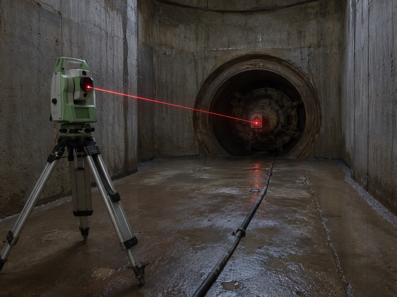
A laser target is a sensor in the machine or lead pipe that reads a laser beam from the launch shaft and reports the machine position against line and grade. A laser target is simple and inexpensive on straight drives and, with a total station, gives continuous data to the control cabin.
Theodolite total station
A theodolite total station measures angles and distances to set and check the tunnel reference line and verify the laser or target system. Modern units track a target automatically, so the surveyor checks line and grade without entering the shaft. A theodolite total station is the independent check on the steering data and appears in the as-built file.
Water leveling
Water leveling uses a water-filled hose or manometer to transfer a level datum with no line of sight, which matters for gravity sewers where grade is critical over long runs. Water leveling is often used to carry the invert level into a deep shaft.
Gyro guidance
Gyro guidance uses a north-seeking gyroscope or inertial unit to find the machine heading and position where laser sight lines cannot reach. Gyro guidance works where there is no clear line to the surface, so it carries the drive through a curve; standard 2.5 m pipes can be jacked to a radius of about 200 m. Gyro guidance is a specification item on any curved or long drive.
Grade
Grade is the designed slope of the pipeline, usually a percentage or a fall in millimeters per meter; for gravity sewers it is the key alignment parameter because flow depends on it. Grade errors are hard to fix after jacking, so grade control is a hold point.
Tolerance
Tolerance is the permitted deviation from design line and level; PJA guidance gives the typical value in Table 2. Tolerance is project-specific: the PJA figure applies to stable, self-supporting ground, and unstable ground or obstructions may force a larger pipe size.
How Do the Jacking and Thrust Terms Fit Together?
These pipe jacking terms cover how the pipe is pushed: jacking frame, thrust wall, thrust ring, packer, jacking pipe, interjack station and jacking force.
Jacking frame
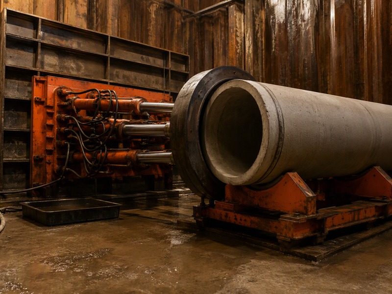
The jacking frame is the reaction structure at the launch shaft that carries the hydraulic rams and pushes the machine and pipe forward. The jacking frame must be aligned with the tunnel axis and strong enough not to move under full jacking force.
Thrust wall
The thrust wall is the reaction surface at the back of the launch shaft that takes jacking force from the rams and transfers it into the ground or shaft. If it moves or fails, the drive loses its reaction and the pipe can go off line. The method statement should show it designed for the maximum jacking force, not just the expected one.
Thrust ring
A thrust ring is the steel collar between the jacking rams and the pipe end that spreads force evenly around the pipe wall so the pipe end is not crushed. A thrust ring stops high jacking force from crushing the pipe end.
Jacking pipe
Jacking pipe is designed to be pushed through the ground, made of reinforced concrete, vitrified clay or other materials to standards such as EN 1916 and BS EN 295-7, with joints that take thrust and stay watertight. PJA guidance gives standard jacking pipe diameters of about 150–2,400 mm, or greater when required. In pipe jacking terms, the pipe class, joint type and allowable jacking load are a technical and a commercial risk.
Interjack station
An interjack station is inserted into the pipe string to split a long drive into shorter, independently pushed sections, reducing the total force and controlling the force on the lead pipe. The interjack station count and spacing decide whether a long drive can be completed.
Jacking force
Jacking force is the total thrust the rams must apply, made up of face resistance plus friction along the pipe. Jacking force can reach hundreds of tonnes on long or large drives, and it sizes the frame, the thrust wall and the pipe class. PJA guidance puts pipe jacking friction typically between 0.5 and 2.5 tonnes per square meter, reducible to 0.1 with lubrication.
Table 1 gives the Pipe Jacking Association indicative jacking length for each nominal internal lining diameter; lengths above 1 km are reported but should only be attempted after a project-specific risk analysis.
Table 1. What jacking length does each nominal internal lining diameter support?
| Nominal internal lining diameter | Indicative achievable jacking length between shafts |
|---|---|
| Under 0.9 m | 150 m |
| 0.9 m | 200 m |
| 1.0 m | 250 m |
| 1.2 m | 450 m |
| 1.35 m | 550 m |
| 1.5 m | 700 m |
| 1.8 m | 900 m |
| 1.9 m or 2.1 m | 1,000 m |
| 2.4 m | 2,000 m |
Which Shaft, Pipe and Settlement Terms Carry the Money?
The final microtunneling terms cover the pits, the pipe, ground movement and price.
Bentonite
Bentonite is a clay-based drilling fluid mixed with water and, in slurry machines, used to support the face and carry spoil, and injected into the annulus to lubricate the pipe. Bentonite holds the bore open, reduces friction and helps control ground loss. Mix, injection points and disposal are method-statement items with real cost.
Launch shaft
The launch shaft is the starting excavation from which the machine is set and jacked, and it must fit the machine, jacking frame, thrust wall and spoil handling. Precast caisson shafts of about 2.4–4 m are described as suitable, and PJA shaft tables cover dry ground to about 15 m sheet piled and about 20 m secant piled.
Reception shaft
The reception shaft is the excavation at the far end that receives the machine and the lead pipe only, so it is usually smaller and simpler than the launch shaft. Confirm the reception eye lets the machine break through safely.
Entry seal (headwall and gland)
The entry seal is the assembly at the launch shaft wall, the headwall opening and gland, that lets the machine and pipe pass out while sealing the gap against groundwater and soil. The entry seal is packed or pressurized so water and ground cannot flow back around the pipe. A poor seal commonly causes shaft flooding and ground loss at the start of a drive.
Ground loss
Ground loss is the volume of soil removed or displaced beyond the intended bore, the main cause of surface settlement above a drive. Ground loss is controlled by good face support, a correctly sized overcut and a well-maintained annulus, and is monitored with surface survey points.
Settlement
Settlement is the downward movement of the surface or structures caused by the drive, controlled by limiting ground loss and overcut. Table 2 gives the published crossing settlement limits. Settlement is managed with a monitoring plan and trigger levels.
Quick reference: values, units and bid wording
On drives we have supported, the argument returns to a handful of these microtunneling terms. Each term above sits inside the broader trenchless terminology, and where ground, length or access rule a drive out, owners compare options such as horizontal directional drilling services.
Table 2 lists only the microtunneling terms whose meaning is a measured quantity or a unit; the remaining definitions are procedural and carry no number. Values are Pipe Jacking Association indicative figures unless the standard is named.
Table 2. Which microtunneling terms carry a number or a unit?
| Term | Why it matters | Typical value or unit |
|---|---|---|
| MTBM | Fixes the ground range, shaft size and guidance | Machine diameter is the pipe bore plus the overcut |
| Pilot tube | Highest accuracy of the systems, usually short drives | About ±1 inch from grade; drives about 120 m or less |
| Overcut | Balances steerability against settlement | 13–38 mm (1/2 to 1.5 in); about 35 mm may cause subsidence |
| Tolerance | Sets machine choice, survey effort and risk | About ±50 mm of true line and level (PJA, stable ground) |
| Jacking force | Sizes the frame, wall and pipe class | Up to hundreds of tonnes; friction 0.5 to 2.5 tonnes per sq m |
| Settlement | Contractual consequence of ground loss | Limited to about 10 mm for road and rail crossings |
Where a term carries three definitions – the contract specification, the named standard and the contractor’s method statement – the order that settles it is specification first, then the named standard, then the method statement. Two definitions of the same term in one tender are a query before bid, not a clarification after award.
Table 3 lists the microtunneling terminology items that most often cause a bid dispute, with the wording that removes the ambiguity.
Table 3. Which terms most often cause a bid dispute, and what wording removes it?
| Term | Who usually misreads it | What to write instead |
|---|---|---|
| Tolerance | Owners treat it as one fixed universal figure | Tie the tolerance to the ground conditions and state the basis |
| Overcut | Bidders price only the minimum gap | State the permitted overcut range with a settlement trigger |
| Jacking force | Designers carry a single constant value | Require a force build-up model allowing for lubrication and interjacks |
| Indicative jacking length | Estimators read it as one clean shaft-to-shaft number | Confirm what the length includes – including the curve allowance – against the table above |
| Jacking pipe | Bidders under-specify the pipe class | State the allowable jacking load, the joint type and the standard |
| Face support | Tenders leave the method open | Require the face-support and spoil-management approach |
| Settlement | Owners set a limit with no monitoring plan | Pair the limit with a monitoring plan and trigger levels |
Frequently asked questions about microtunneling terms
These answers use plain microtunneling terminology.
What does MTBM stand for?
MTBM stands for microtunnel boring machine. The MTBM is the remotely operated, steerable machine that excavates the face and is pushed forward by the pipe string behind it; its type and diameter fix the ground range, shaft size and guidance system.
What is the difference between a slurry shield and an EPB machine?
A slurry shield supports the face with pressurized slurry, while an EPB machine supports it with conditioned excavated soil. Slurry suits saturated, variable and rock ground and needs a separation plant; EPB suits cohesive soils and is common on larger pipe jacks.
What is overcut in microtunneling?
Overcut is the small annular gap cut ahead of the machine so the pipe can be steered and friction controlled. For anyone asking whether overcut and settlement are the same thing, the distinction is that overcut is a dimension the machine cuts while settlement is the surface movement it can cause.
What is the typical tolerance for microtunneling?
PJA guidance gives a typical tolerance of about plus or minus 50 mm of true line and level at any point in stable, self-supporting, homogeneous ground. For a specification clause, state the ground condition the value is tied to, the basis for measuring it, and who carries the risk if it is exceeded.
What is an interjack station used for?
An interjack station splits a long drive into shorter, independently pushed sections so the total jacking force and the force at the lead pipe stay within limits. Interjack stations are one of the main reasons drives can exceed 1 km.
What is the difference between a launch shaft and a reception shaft?
The launch shaft is where the machine is set and jacked, so it carries the jacking frame, thrust wall and spoil or slurry handling. The reception shaft only receives the machine and the lead pipe and is usually smaller and simpler.
Key Takeaways
- In a tender, the terms that decide money are tolerance, overcut, jacking force and jacking pipe class: define those four in the specification and leave the rest to the standard.
- This microtunneling glossary works best when each term carries a number: overcut and tolerance in millimeters, jacking force in tonnes, settlement in millimeters.
- Most disputes in pipe jacking terms trace back to tolerance, overcut, jacking force, drive length and jacking pipe, so those definitions belong in the specification.
- Ground conditions, not preference, decide most of these entries, and the same trenchless terminology means different things in unstable ground.
- Our field teams record settlement and guidance readings against the triggers set at design.
How JSW Supports Microtunneling Projects
JSW is a pipeline engineering and construction company that executes trenchless crossings with its own crews and equipment. Our scope covers microtunneling construction, trenchless technologies, pipeline inspection service and pipeline installation services.
We install pipelines from DN300 to DN1500 (12 to 60 inches) by microtunneling, with single drives up to 600 m, laser guidance accuracy of about ±25 mm, and depths of about 2 to 25 m. Our ground range runs from soft clay and sand through cobbles and mixed ground to hard rock up to about 80 MPa UCS, and we deploy interjack stations roughly every 100 to 150 m. We work to ISO 9001:2015, ISO 14001:2015 and ISO 45001:2018.
If a term in your specification needs clarifying, our engineers work from the same definitions in this glossary and will walk your team through the microtunneling glossary, the pipe jacking terms and the wider trenchless terminology before you bid.
- Integrated delivery: one team for survey, shaft construction, jacking, guidance and reinstatement.
- Auditable process data: jacking force, guidance and settlement readings recorded through the drive.
- Risk-explicit pricing: assumptions on ground, drive length and shafts stated up front.
- Safety and compliance: remote, no-man-entry operation under recognized certification.
Reading a microtunneling specification and need to know what a term requires in practice? Send your drive schedule, diameter and geotechnical summary for a free technical review. Our engineers reply with a note on each term your specification relies on, the values it should carry, and an indicative budget range.





































 English
  Arabic
  Russian
  Spanish
  French
  Vietnamese
  Polish
  Thai
Thai  Indonesian
  Turkish
  Portuguese