
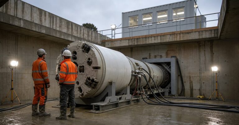
A microtunneling inspection and test plan (ITP) is the document that defines, before mobilization, what will be inspected and tested, by whom, at which stage, and what evidence closes each item. It turns equipment readiness from opinion into recorded hold points, which makes it the cheapest risk control on a microtunneling project. Within that plan, a hold point stops the work until the item is released, a witness point records attendance while work continues, and a commissioning checklist is one record that closes the equipment items on the plan.
This guide sets out the three gates a microtunneling spread has to pass – factory acceptance, site acceptance after reassembly, and shaft readiness in the last day before launch – explains how hold points, witness points and records are structured, lists what should be tested on the machine and on the support equipment, shows how jack commissioning and alignment checks are verified, and closes with a master checklist and the ten findings that most often stop or delay a launch, written for owners signing off the works, contractors assembling the bid, and EPC teams coordinating several drives at once.
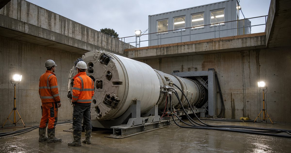
What Should Be Tested Before a Microtunneling Drive Starts?
Before a drive starts, three things have to be proven: that the machine and its support equipment work individually, that they work together as a system after reassembly on site, and that the set-up in the shaft is correct on line, grade and level. A microtunneling inspection and test plan expresses those three proofs as gates with defined release points, so launch is a release decision, not a scheduled date.
The reason to structure readiness testing as gates is asymmetric cost. Testing a face pressure control loop in a workshop costs an afternoon; discovering that it will not hold pressure once the machine is at the face costs a drive. In our experience, most pre-launch findings are items nobody was assigned rather than equipment failures, which is what an inspection and test plan exists to prevent.
The Three Gates: Factory, Site Mobilisation, Shaft Readiness
A gate here is a staged check with its own evidence, not a physical gate. Factory, site and shaft readiness gates differ in what can be tested, who can witness it, and what each can prove. Factory acceptance proves the equipment functions to specification in a controlled environment with the manufacturer present; site acceptance proves the reassembled system works on site power and water; shaft readiness proves the geometry, seal and pipe supply before launch, which cannot be verified anywhere else.

| Gate | What it proves | What it cannot prove | Evidence |
|---|---|---|---|
| 1. Factory acceptance test | Machine and support equipment function to specification; instrumentation reads and logs | Site reassembly, site power quality, actual ground interface | Test records, calibration certificates, instrument logs, non-conformance close-outs |
| 2. Site acceptance | System works as assembled on site, with site power, water and slurry circuits | Shaft geometry, entry seal fit, final alignment | Function test records, pressure and flow readings, signed check sheets |
| 3. Shaft readiness | Machine and cradle on line, grade and level; seal built to design; pipe available | Ground behavior ahead of the face | Survey record, seal inspection, set-out verification, pipe delivery records |
Building the Inspection and Test Plan: Hold Points, Witness Points, Records
Published specification practice requires the microtunneling inspection and test plan to be prepared and submitted for approval about four weeks before the start of microtunneling works, with at least 48 hours’ notice (a typical published submission and notice period; confirm the contract’s own period and any shorter agreed notice) for a required visual inspection, witness point verification or hold point release. The notice requirement matters on a compressed program: an unrecognized hold point can idle a crew for a day.
Applies to microtunneling drives delivered under a contract specification. Where the works are delivered only to a supplier’s procedure, the point types and notice periods are set by that procedure and the contract, not by this guide; the periods quoted here are typical published practice and must be confirmed against the contract.
- Visual inspection. Work continues while the item is looked at. Suitable for set-out of the jacking frame, seal installation and general site readiness.
- Witness point. Work may continue, but attendance is recorded. Used where the outcome is repeatable and the consequence of a miss is recoverable.
- Hold point. Work stops until the item is released. Reserved for irreversible or hidden works – shaft construction, jacking wall block set-out, machine commissioning, entry seal, and alignment verification before launch.
- Records. Every point is closed by a document: a test record, a survey sheet, a commissioning checklist line, a calibration certificate or a signed inspection sheet. An unrecorded check is not a check.
Two categories of documentation carry hold points before any equipment is tested. Project documentation items include the quality, safety and environmental plans, dilapidation reports, the site establishment and settlement plans, and the tunneling, pipe installation and grouting procedures. Design documentation items include the crane pad, the shaft, the jacking frame and thrust wall, and the machine including its airlock and head.
| Element | Typical activity | Point type | Closes with |
|---|---|---|---|
| Project documentation | Quality, safety and environmental plans; tunneling and pipe installation procedures | Hold | Approved documents |
| Design documentation | Shaft, jacking frame and thrust wall, machine including airlock and head | Hold | Approved design, check certificates |
| Execution | Shaft mark-out and construction to design | Witness or hold | Survey record |
| Execution | Jacking frame and jacking wall block set-out | Hold | Set-out verification |
| Execution | Machine entry seal built to design | Hold | Inspection record |
| Execution | Machine commissioning: mechanical, electrical, hydraulics | Hold | Commissioning records |
| Execution | Jack commissioning | Witness | Pressure and stroke test records |
| Execution | Machine and lead pipe alignment checks | Hold | Survey record against design line and grade |
| Execution | Settlement monitoring and review | Witness | Monitoring readings |
Gate 1 – Factory Acceptance and Workshop Testing
Factory acceptance tests the machine and the support equipment before shipment, while the manufacturer’s technicians are still on site and while lifting and access are simple. A commissioning checklist should be written before the machine arrives, so the tests are set by the people who will rely on the results; in our commissioning work, every line is signed by the person who performed the test and closed with a record or certificate; the acceptance criteria remain project-specific inputs to confirm against the contract specification and the supplier’s procedure.
The single most valuable test is proving that every instrument reads and logs what it is supposed to, because instruments are what the operator will rely on for the whole drive. The factory acceptance test is also the last point at which a missing commissioning checklist item can be added without delaying shipment.
Testing the machine
Published specification practice sets a minimum instrument set that should be demonstrated working: face pressure gauges; cutterhead rotation speed, direction, torque and thrust gauges; slurry flow and pressure gauges on a slurry machine, or screw rotational speeds and pressure drops on an earth-pressure-balance machine; electrical power; advance rates; a means of measuring and recording the volume of material excavated per pipe; and cutterhead door aperture status where fitted.
- Mechanical, electrical and hydraulic commissioning as a combined test, not three separate sign-offs.
- Face pressure control range and stability, with confirmation that pressure can be adjusted to suit changing face conditions and maintained within about 10% of the required value.
- Steering function through the articulated joint, with roll correction verified.
- Cutterhead operation and torque selection, including the low, medium and high torque settings where the machine offers them.
- Instrumentation and logging, including the data points the operator will record each shift.
- Seals: tail seals designed to withstand the maximum hydrostatic pressure at the tunnel invert plus additional pressure from propulsion and slurry, with an adequate safety margin, preventing ingress of water, slurry and other materials into the finished lining.
Testing the support equipment
Support equipment is often accepted on supplier paperwork alone, which is a mistake: it transfers the load and cools, lubricates and measures the drive. Each support item should carry its own commissioning checklist line, not be covered by the machine’s sign-off.
- Factory acceptance test on the jacking frame, including cylinder grouping, stroke and the calibrated pressure gauges that must allow actual jacking force to be read at any time.
- Thrust ring geometry checked against the pipe outside diameter, and rigidity verified, because the ring’s job is even load distribution.
- Power pack and pumps tested against the flow and pressure envelope they will be run at, not only their ratings.
- Separation plant tested for throughput, screen deck condition and hydrocyclone assembly, since capacity is what the drive will be limited by.
- Guidance instruments and targets checked, calibrated and matched to the machine’s target mounting.
- Lubrication injection system function-tested against its set volume or set pressure behavior.
Gate 2 – Site Acceptance: Reassembly, Alignment and Function Tests
A passed factory acceptance test does not replace site acceptance. A machine is not the same system once dismantled, transported and rebuilt, so this gate repeats the tests that reassembly can invalidate and runs the system on site power and water.
- Reassembly inspection against the manufacturer’s procedure, including bolted and hydraulic connections, seal faces and cable routing.
- Power and control checks on site supply, including the control container, communications to the machine and the emergency stop chain.
- Slurry or spoil circuit testing with feed, booster and return pumps, flow meters and pressure sensors, confirming that the abrasion-resistant sensors on feed and discharge lines read correctly and can be replaced under operating conditions.
- Guidance set-up: shaft station on line and grade behind the jacking frame and protected from disturbance, target and inclinometer readings verified, and control points re-shot against permanent benchmarks.
- Commissioning checklist sign-off, with each item signed by the person who performed it and not only by the party that benefits from it.
Gate 3 – Shaft Readiness: The Last Day Before Launch
The shaft readiness gate is short and unforgiving: it checks geometry, sealing and the availability of what the drive will consume, and it is the last chance to find a problem while the machine is still recoverable by crane.
Pre-launch checks in a pipe-jacking shaft come down to four proofs: the machine and cradle are on line, grade and level; the entry seal is built to design; jack commissioning has shown thrust pressure, stroke position and stroke speed are measurable; and adequate jacking pipe is on site.
- Alignment verification: the jacking cradle and machine are verified set on line, grade and level before launch.
- Jack commissioning as a witnessed item, with thrust pressure, stroke position and stroke speed demonstrably measurable.
- Machine and lead pipe alignment checks recorded against the design line and grade.
- Entry seal built to design and inspected for concentricity and seal condition.
- Pipe availability: tunneling should only commence when there is adequate jacking pipe available.
- Consumables and spares staged: bentonite or polymer, cutter tooling, seals, hoses and a spare pump on site, not on order.
- Intervention procedure: where cutter change or head intervention may be needed, the procedure is approved and on site before launch and states where work stops until the item is released.
The Master Checklist and the Findings That Delay Launches
The master equipment readiness checklist below is the working core of the microtunneling inspection and test plan: fifteen items, each mapped to a gate, an evidence document and a point type, so no item can be closed on opinion. This is the form we use on site, and it is deliberately short enough to be walked through in an hour.
| Item | Gate | Evidence | Point type |
|---|---|---|---|
| Quality, safety, environmental and commissioning procedures approved | Pre-start | Approved documents | Hold |
| Shaft, jacking frame and thrust wall design approved | Pre-start | Approved design and calculations | Hold |
| Machine commissioning: mechanical, electrical, hydraulics | 1 / 2 | Commissioning records | Hold |
| Minimum instrument set demonstrated reading and logging | 1 | Instrument log | Witness |
| Face pressure control held within the required band | 1 / 2 | Pressure test record | Hold |
| Jacking frame cylinders, stroke and gauges verified | 1 | Test record and calibration certificates | Witness |
| Thrust ring geometry and rigidity checked against pipe | 1 / 3 | Inspection record | Witness |
| Separation plant throughput and screens verified | 1 / 2 | Throughput test record | Witness |
| Guidance set-up on line and grade; control points re-shot | 2 / 3 | Survey record | Hold |
| Entry seal built to design and inspected | 3 | Inspection record | Hold |
| Jacking cradle and machine on line, grade and level | 3 | Survey record | Hold |
| Jack commissioning with pressure, stroke and speed measured | 3 | Test record | Witness |
| Adequate jacking pipe available on site | 3 | Delivery records | Visual |
| Spares, tooling and consumables staged | 3 | Stores check sheet | Visual |
| Intervention procedure available where required | Pre-start / 3 | Approved procedure | Hold |

Across the drives we have supported, the same group of findings recurs: instrumentation that reads but has never been calibrated; an entry seal not concentric or properly seated; alignment set by tape and level, not a survey record; guidance not checked against control points after shaft completion; thrust gauges read as ram pressure without conversion to jacking force; spares assumed staged but not there; slurry line sensors that cannot be replaced under pressure; interjack stations never brought into readiness; a separation plant never run at throughput; and a cutterhead tooling list never reconciled against the logged ground.
Bottom line: a microtunneling inspection and test plan is worth exactly what its records are worth. An item is on the plan only when a document closes it; everything else is a hope, not a check.
Equipment-specific checks are covered in more depth in our guides to microtunnel boring machines, guidance systems and jacking frames, all of which feed the same microtunneling inspection and test plan.
Key Takeaways
- A microtunneling inspection and test plan should be submitted for approval about four weeks before works start, with at least 48 hours’ notice for inspections, witness points and hold points.
- Three gates cover the drive: factory acceptance, site acceptance after reassembly, and shaft readiness before launch.
- Hold points stop work and belong on irreversible or hidden items; witness points record attendance while work continues.
- The minimum machine instrument set has to be demonstrated working and logging, not merely installed.
- Face pressure control must be adjustable to changing face conditions and maintainable within about 10% of the required value.
- Before launch, the jacking cradle and machine must be verified on line, grade and level, the entry seal built to design, jack commissioning witnessed, and adequate jacking pipe on site.
Frequently Asked Questions
What is a microtunneling inspection and test plan?
A microtunneling inspection and test plan (ITP) is the document that defines what is inspected and tested, by whom, at which stage, and what evidence closes each item. Published specification practice requires it to be submitted for approval about four weeks before microtunneling works start, with defined visual, witness and hold points.
What is the difference between a hold point and a witness point?
A hold point stops the work until the item is released; a witness point allows work to continue but records attendance. Both form part of the same microtunneling inspection and test plan, and both require advance notice.
What should be tested on the machine before shipment?
Mechanical, electrical and hydraulic commissioning, instrumentation function, and cutterhead operation. The minimum instrument set – face pressure gauges, cutterhead speed, direction, torque and thrust gauges, slurry flow and pressure gauges or screw speed and pressure drop instruments, advance rate, excavated volume measurement and cutterhead door status where fitted – should be demonstrated working, not merely fitted.
What has to be verified in the shaft before launch?
The jacking cradle and machine must be set on line, grade and level, and the entry seal built to design. Published practice also requires jack commissioning, machine and lead pipe alignment checks, and confirmation that adequate jacking pipe is available before tunneling commences.
How much notice does a hold point need?
Published practice requires at least 48 hours’ notice for a required visual inspection, witness point verification or hold point release. Notifying several items together reduces the number of stoppages on a short mobilization program.
What are the most common pre-launch findings?
Instrumentation that reads but has not been calibrated, an entry seal that is not concentric or not properly sealed, and incomplete alignment verification against the design line and grade. Also common are guidance that has not been checked against control points, spares that were never staged, and thrust gauges that do not read true jacking force.
How JSW Supports Equipment Readiness and Commissioning
JSW is a pipeline engineering and construction company that executes trenchless crossings with its own crews and equipment. Our scope covers microtunneling construction, trenchless technologies, HDD crossing services, pipeline installation services and pipeline inspection services. We run commissioning and hold-point discipline on every drive rather than relying on supplier paperwork.
The same team commissions the machine and then operates the drive, so records stay consistent from factory test to as-built. Where an item cannot be closed, it is raised before launch, when it is still cheap to fix.
- Records, not recollections: every item closed with a test record, survey sheet or calibration certificate.
- Three-gate discipline: factory, site and shaft gates applied with named release points on the irreversible items.
- Installed capability: instrumentation, seals, guidance and the separation plant are proven in situ rather than on datasheets.
- Certified delivery: our trenchless work is delivered under ISO 9001:2015, ISO 14001:2015 and ISO 45001:2018 certified management systems.
Want an independent check that your equipment and records are actually launch-ready? Send your equipment list, commissioning records and program dates for a free technical review. Our engineers respond with a scoped readiness assessment and an indicative budget range.





































 English
  Arabic
  Russian
  Spanish
  French
  Vietnamese
  Polish
  Thai
Thai  Indonesian
  Turkish
  Portuguese