
Burn-through is the failure that occurs when the weld pool melts through the remaining pipe wall of a live pipeline and the internal pressure blows out the weakened area. To prevent burn-through when welding live pipelines, you must verify the remaining wall thickness first, weld to a qualified in-service welding procedure, keep heat input low with stringer beads, and let the flowing product carry heat away. This guide explains the burn-through mechanism, the four risk factors that drive it, eight field-proven prevention methods with welding parameters, the standards that govern the work (API Standard 1104, API RP 2201, ASME PCC-2, NACE MR0175/ISO 15156-2), and a step-by-step field procedure you can apply on your next job.
In this guide:
- What Is Burn-Through When Welding Live Pipelines?
- Why Does Burn-Through Happen? Four Main Risk Factors
- How to Prevent Burn-Through: 8 Proven Methods
- What Does a Burn-Through Prevention Field Procedure Look Like?
- Direct Fillet Weld vs. Full Encirclement Saddle vs. Hot Tap Split Tee
- Frequently Asked Questions About Live Pipeline Welding
- Conclusion
- Sources and References
Key Takeaways
- Measure the remaining wall with UT before the first bead; 6.4 mm (0.25 in) is the conservative engineering threshold, and 4 mm is the research-validated lower limit for controlled in-service welding.
- Keep heat input at 1.0 kJ/mm or below on 4.0-6.4 mm walls; up to 1.5 kJ/mm is allowed only on walls of 6.4 mm or more, and only per a qualified WPS.
- Deposit stringer beads with 2.4-3.2 mm electrodes; never weave or use oversized rods on thin walls.
- Verify flow before welding; dead legs are the highest-risk locations because nothing carries heat away.
- Preheat to at least 100 °C (212 °F) when the surface is wet, when moisture is present, or when the product contains hydrogen sulfide.
- Inspect after welding with MT/PT and cap hardness at 22 HRC for sour service per NACE MR0175/ISO 15156-2.
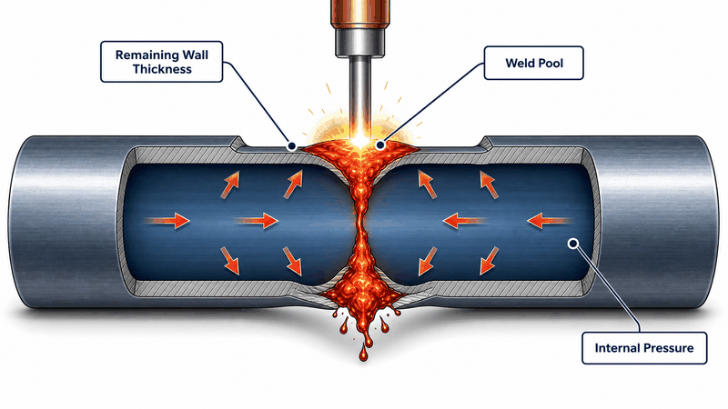
Figure 1. Burn-through occurs when the weld pool penetrates the remaining wall of a pressurized pipe and internal pressure ruptures the molten zone.
What Is Burn-Through When Welding Live Pipelines?
Burn-through is the sudden rupture of the pipe wall at the weld location while the line is still under pressure. When the arc melts the remaining wall completely, the weld pool loses its load-carrying capacity, and the internal pressure pushes the molten metal outward, creating a hole or a violent blowout.
The failure is not a simple “welding too hot” problem. It is the combined result of heat input, remaining wall thickness, internal pressure, and the cooling effect of the flowing product.
The molten pool behaves like a volumetric defect in the wall, and burn-through occurs when the residual strength of the wall under the pool can no longer support the internal pressure. Two independent research criteria describe when that point is reached:
- Deformation criterion: burn-through is defined as occurring when radial deformation of the wall exceeds 0.1 times the wall thickness, a limit used in PRCI research on in-service welding criteria and in EWI’s In-Service Welding Guidelines.
- Temperature criterion: TWI research and PRCI hot tap thermal analysis cite 982 °C (1800 °F) as the critical internal wall temperature for burn-through, a limit established in Battelle’s in-service welding studies on API X-series pipeline steel.
These two criteria explain why thin walls, high pressure, and low flow are the dangerous combination. In practice, stop welding if either criterion approaches its limit: deformation is visible before temperature can be read.
Why Does Burn-Through Happen? Four Main Risk Factors
Burn-through risk is controlled by four variables, and they multiply each other. A thin wall alone is manageable with low heat input. A thin wall at high pressure with no flow is an accident waiting to happen.
- Thin remaining wall: corrosion, erosion, or mill tolerance reduces the wall that can absorb heat before melting.
- High internal pressure: pressure is the driving force that blows out the molten zone once penetration occurs.
- Low or no flow (dead legs): a stagnant product cannot carry heat away, so the wall temperature climbs far faster.
- High heat input or poor technique: weaving, oversized electrodes, and slow travel speed concentrate heat on one spot.
| Risk factor | Why it matters | Primary control |
|---|---|---|
| Remaining wall below the conservative 6.4 mm (0.25 in) threshold | The wall cannot absorb welding heat without melting through | UT survey before welding; use a full encirclement fitting or shut down the line |
| High operating pressure | Pressure converts a small melt-through into a blowout | Reduce pressure where the operation permits; keep flow for cooling |
| Dead leg or stagnant section | No heat removal; inner-wall temperature rises rapidly | Verify flow, or weld with the lowest heat input in the qualified range |
| Excessive heat input | Melts more wall metal and raises inner-wall temperature above safe limits | Stringer beads, 2.4-3.2 mm electrodes, no weaving, heat input log |
How to Prevent Burn-Through: 8 Proven Methods
These eight methods work together. Skipping one does not double the risk of the others; it multiplies it. Every method below has been validated in hot tap projects and in research by EWI and Battelle, governed by API standards.
1. Measure the Remaining Wall Thickness Before You Weld
Burn-through prevention starts before the first bead. A thickness survey with ultrasonic testing (UT) identifies thin spots caused by corrosion, erosion, or manufacturing tolerance, so you never weld on a wall that cannot take the heat.
Industry practice treats 6.4 mm (0.25 in) as a conservative engineering threshold for direct in-service welding with low-hydrogen electrodes and normal welding processes, a figure reflected in procedure qualification practice under API Standard 1104 (24th ed., 2021). EWI experiments showed that a 4 mm minimum wall is weldable when a 3.2 mm electrode is used at 110 A with a heat input of 0.9 kJ/mm.
Below 4 mm, direct welding should not be attempted without a full encirclement fitting or other engineered solution. The distinction matters in the field: 6.4 mm is the conservative threshold, while 4 mm is the lower limit demonstrated in controlled research.
| Remaining wall thickness | Recommended approach for live pipeline welding |
|---|---|
| 6.4 mm (0.25 in) or more | Direct welding to a qualified WPS is generally accepted |
| 4.0-6.4 mm (0.16-0.25 in) | Direct welding only with low heat input (1.0 kJ/mm or less), stringer beads, and flowing product; 4 mm is the research-validated lower limit (EWI test: 110 A, 0.9 kJ/mm) |
| Below 4.0 mm (0.16 in) | Do not weld directly; use a full encirclement saddle/fitting, or take the line out of service |
Download the burn-through prevention checklist to take these thickness rules into the field.
2. Weld to a Qualified Procedure (WPS) Built for In-Service Welding
A procedure qualified for pipeline tie-ins is not a procedure for welding on a pressurized pipeline. The welding procedure specification (WPS) for live pipeline welding must be qualified with the actual wall thickness range, pressure, flow condition, electrode class, and heat input ceiling you will use on site.
API Standard 1104 (24th ed., 2021) covers qualification of welding procedures for in-service pipelines, and ASME PCC-2-2022 provides guidance for repair of pressure equipment and piping.
The qualified procedure should state the maximum heat input, the minimum and maximum preheat and interpass temperature, the electrode type (typically low-hydrogen E7018 or equivalent), and the pressure and flow conditions that were present during qualification. Never improvise.
If the site conditions differ from the qualified range, the procedure must be re-qualified or the job stopped.
3. Keep Heat Input Low and Use Stringer Beads
Heat input is the single variable you control bead by bead. It is calculated as:
Heat input (kJ/mm) = 60 x Volts x Amps / (1000 x travel speed in mm/min)
Lower amps, higher travel speed, and smaller electrodes all reduce heat input. As a tiering rule, keep heat input at 1.0 kJ/mm or below when the remaining wall is in the 4.0-6.4 mm range; heat input up to 1.5 kJ/mm is acceptable only on walls of 6.4 mm or more, and only when the WPS is qualified for that value.
The field practices that protect thin walls are simple and proven:
- Use 2.4 mm (3/32 in) or 3.2 mm (1/8 in) electrodes, never larger.
- Deposit thin stringer beads with no weaving or oscillation.
- Keep amperage in the lower half of the electrode range; the EWI reference test used 110 A at 0.9 kJ/mm.
- Allow each bead to cool before the next one starts.
| Parameter | Typical range for live pipeline welding | Reason |
|---|---|---|
| Electrode diameter | 2.4 mm or 3.2 mm (3/32 in or 1/8 in) | Smaller electrodes deliver lower current density and shallower penetration |
| Welding current | 90-130 A (SMAW, low-hydrogen) | Keeps heat input within the qualified ceiling (1.0 kJ/mm or less on 4.0-6.4 mm walls) |
| Bead technique | Stringer beads only, no weave | Weaving holds the arc on one spot and raises inner-wall temperature |
| Heat input ceiling | 1.0 kJ/mm or less for 4.0-6.4 mm walls; up to 1.5 kJ/mm for walls of 6.4 mm or more per qualified WPS | Keeps peak inner-wall temperature below burn-through thresholds |
| Interpass | Cool to hand-touch between passes | Lets the flowing product carry accumulated heat away |
4. Use the Flowing Product to Carry Heat Away
The product inside the pipe is your best cooling system. A flowing medium removes heat from the inner wall continuously, which is why live line welding is safer on flowing lines than on idle ones.
Dead legs and stagnant sections are the highest-risk locations. Heat accumulates with every pass because nothing carries it away, and the inner-wall temperature can cross the 982 °C (1800 °F) research threshold within a single pass.
Before welding, verify that the section is flowing, and where possible maintain flow even if pressure must be reduced. On our hot tap projects, we confirm flow direction and velocity on the job sheet and refuse to weld on confirmed dead legs without re-qualifying the procedure for zero-flow conditions.
5. Control Preheat and Interpass Temperature
Preheat on a live line serves two purposes: it dries moisture and it slows cooling to prevent hydrogen cracking. But on a thin wall under pressure, excessive preheat works against you by adding heat to a wall that is already difficult to cool.
Common practice, consistent with API RP 2201 (5th ed.) guidance for hot tapping work, is to preheat to at least 100 °C (212 °F) when the surface is wet, when moisture is present, or when the product contains hydrogen sulfide. Beyond that, let the flowing product do the cooling.
Between passes, allow the weld to cool toward the preheat minimum before depositing the next bead, and monitor the temperature with contact thermocouples rather than guessing.
6. Use Welders Qualified for In-Service Welding
The best procedure fails in the hands of an unqualified welder. Welders on live pipeline welding jobs must hold current qualification per API 1104, including the in-service welding requirements, and should have a proven record on hot tap work.
Technique matters as much as parameters. A steady travel speed, a consistent arc length, and the discipline to stop and cool rather than “finish the bead” are what separate safe welds from burn-through events. In our experience, a welder who has burned through once rarely repeats it after retraining, but a welder who has never welded on pressure is a liability regardless of certificates.
7. Use Full Encirclement Fittings or Hot Tap Fittings on Thin or Corroded Pipe
When the wall is too thin for direct welding, the solution is to change the geometry instead of the parameters. A full encirclement saddle (also called a full encirclement fitting) wraps around the pipe and increases the effective thickness at the weld location, so the fillet weld is deposited onto a heavier section that can absorb the heat.
For branch connections, a hot tap split-tee fitting performs the same function: the tee body carries the load, and the seal welds are located on thicker effective sections. These fittings, together with hot tapping equipment such as drilling machines and line stopping plugs, convert a high-risk welding job into a controlled procedure. The fitting itself must be selected for the pipe diameter, pressure class, and product service.
For line stopping work, the same wall-thickness logic applies to the stopper fitting welds. If you need the full workflow, our hot tapping and line stopping services cover procedure qualification, fitting supply, and execution.
8. Monitor, Inspect, and Test During and After Welding
Monitoring turns prevention into a closed loop. During welding, contact thermocouples track the surface temperature at the weld location, and the welder watches for the early signs of burn-through: localized overheating, sagging, or deformation of the wall. The 0.1-times-wall-thickness radial deformation limit established by EWI and PRCI research gives a clear criterion: visible deformation means stop immediately.
After welding, the completed weld is inspected and tested to confirm integrity:
- Visual testing (VT) of every bead.
- Magnetic particle testing (MT) or penetrant testing (PT) of the completed weld.
- UT thickness checks around the weld area.
- Hardness testing to control hardness in sour service, typically capped at 22 HRC per NACE MR0175/ISO 15156-2:2015, to confirm the heat-affected zone is not hard and crack-prone.
We log heat input for every bead on live line welding work and keep the records with the job file. When a client asks how we prevented burn-through on a 12-inch gas hot tap with a wall above 6.4 mm, the answer is in the log: measured wall thickness, qualified procedure, 0.9-1.1 kJ/mm per bead (within the qualified ceiling for that wall), flow confirmed, every pass cooled, and a full MT plus hardness report at the end.
Download the burn-through prevention checklist and compare your own job controls against it.
What Does a Burn-Through Prevention Field Procedure Look Like?
The following ten-step sequence is the workflow our crews use on live pipeline welding and hot tapping jobs. It is written so any engineer or supervisor can adapt it to their own qualified procedures.
- Review as-built drawings and inspection records; confirm the pipe grade, diameter, and wall thickness.
- Run a UT survey over the weld area and map the minimum remaining wall thickness.
- Confirm the product, operating pressure, temperature, and flow condition; flag dead legs.
- Select the connection method: direct fillet weld, full encirclement saddle, or hot tap split tee.
- Verify that the WPS and the welder are qualified for the exact conditions on site.
- Prepare the surface: remove coating, corrosion products, and moisture down to sound metal.
- Preheat to the procedure minimum (typically 100 °C) when moisture or hydrogen sulfide is present; monitor with thermocouples.
- Deposit stringer beads at the qualified heat input; cool between passes and watch for deformation.
- Stop immediately if the wall sags, the weld zone overheats, or radial deformation approaches the limit.
- Inspect and test the completed weld (VT, MT/PT, hardness, UT as required) and record all data.
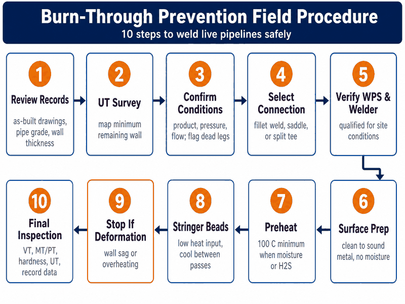
Figure 2. The ten-step burn-through prevention workflow used on live pipeline welding jobs.
Direct Fillet Weld vs. Full Encirclement Saddle vs. Hot Tap Split Tee: Which One Prevents Burn-Through Best?
Choosing the right connection method is a prevention decision made before the arc strikes. Each method has a clear application window.
| Method | Best for | Burn-through risk | Typical use |
|---|---|---|---|
| Direct fillet weld (branch or pad) | Wall 6.4 mm and above (conservative threshold), sound metal, flowing line | Moderate; controlled by heat input | Small branches, instrument connections, temporary taps |
| Full encirclement saddle | Thin or corroded wall, uncertain thickness, high pressure | Low; saddle adds effective thickness | Repairs, reinforcement of thin-wall piping, line stopping installations |
| Hot tap split tee | New branch connections on operating lines | Low; seal welds located on heavier sections | Hot tapping for new offtakes without shutdown |
Frequently Asked Questions About Live Pipeline Welding
Can you weld on a live gas pipeline?
Yes. Welding on live gas pipelines is a routine, code-controlled operation known as in-service welding or hot tapping. It is performed to a qualified WPS per API 1104, with low-hydrogen electrodes, controlled heat input, and verified flow. The line is not depressurized, which is the entire point of the technique, so the procedure must be engineered for the actual pressure and flow.
What is the minimum wall thickness for welding on live pipelines?
The conservative engineering threshold used across the industry is 6.4 mm (0.25 in) for direct in-service welding with low-hydrogen electrodes and normal welding processes. EWI research demonstrated that a 4 mm wall can be welded with a 3.2 mm electrode at 110 A and 0.9 kJ/mm heat input. Below 4 mm, direct welding is not recommended; use a full encirclement fitting or take the line out of service.
Do you need preheat before welding on a live pipeline?
Preheat is required when the surface is wet, when moisture is present, or when the product contains hydrogen sulfide; 100 °C (212 °F) is the common minimum. On dry, clean carbon steel with adequate flow, preheat may be minimal, because the flowing product provides cooling and the low heat input limits the cooling rate problem. The WPS determines the exact requirement.
What happens if burn-through occurs during welding?
Burn-through produces an immediate leak or blowout at the weld location. The correct response is to stop welding, remove the heat source, and isolate the section per the emergency response plan. The leak is then controlled by line stopping or shutdown, and the affected area is repaired with a full encirclement fitting after the line is safe. Burn-through is why the procedure, the wall thickness survey, and the welder qualification all matter before the first bead.
Is burn-through risk higher when the pipeline is idle?
Yes, significantly. Without flowing product, no heat is carried away from the inner wall, so the wall temperature climbs with every pass. Dead legs and idle sections are treated as high-risk locations and are welded with the lowest qualified heat input, or re-qualified for zero-flow conditions, or avoided entirely.
Do hot tapping and live pipeline welding require special equipment?
Yes. In addition to the welding equipment, hot tapping requires a drilling machine, a tapping valve, and line stopping plugs, while the fitting itself (split tee or full encirclement saddle) must match the pipe size and pressure class.
Automatic welding systems with real-time heat input monitoring are increasingly used on large-diameter work because they hold parameters more consistently than manual welding. Equipment alone does not prevent burn-through; the procedure, the thickness survey, and the welder qualification do.
Can you weld on a live oil pipeline?
Yes. Live oil lines are welded with the same in-service controls as gas lines: a qualified WPS, low heat input, stringer beads, and verified flow. Liquid product carries heat away effectively, often better than gas, because of its higher heat capacity. The additional focus on oil work is fire safety: the work area must be free of leaks, oil mist, and vapor, and hot work permits are typically mandatory.
What is the heat input limit for in-service welding?
There is no single universal limit; the ceiling is defined by the qualified WPS for your wall thickness. As a working rule, keep heat input at 1.0 kJ/mm or below when the remaining wall is in the 4.0-6.4 mm range, and allow up to 1.5 kJ/mm only on walls of 6.4 mm or more with a WPS qualified for that value. The practical limit is the one that keeps the inner-wall temperature below about 982 °C (1800 °F), the threshold identified in Battelle’s in-service welding research.
Is in-service welding on pipelines dangerous?
Any in-service welding on a pressurized pipeline carries risk, and burn-through is the primary hazard because a melt-through can release the product immediately. The risk is managed, not eliminated: wall thickness measurement, a qualified procedure, heat input control, and verified flow reduce it to a level that the industry routinely accepts. A confirmed dead leg, an unmeasured thin wall, or an unqualified welder turns an acceptable risk into an unacceptable one.
Burn-through vs. blowout: what’s the difference?
Burn-through is the event: the weld pool melts through the remaining wall and the internal pressure ruptures the molten zone. Blowout is the severe consequence, when the sudden release of pressurized product physically ejects weld metal and opens a large hole. Every blowout begins with a burn-through, but not every burn-through escalates into a blowout, which is why stopping at the first sign of deformation matters.
Not sure if your wall thickness is weldable? Send us your UT readings. Our engineers will tell you whether you can weld directly or need a fitting, usually within 24 hours.
Burn-through when welding live pipelines is preventable, but only with a system: measure the wall, qualify the procedure, control the heat input, use the flow, and inspect the result. The eight methods in this guide are not optional extras; they are the minimum engineering discipline for safe live pipeline welding, supported by API standards and research from EWI and Battelle and proven across thousands of hot tap jobs worldwide.
If you are planning hot tapping, line stopping, or any welding on an operating pipeline, work with a specialist who can qualify the procedure, supply the fittings and equipment, and put experienced welders on the job. JSW has completed more than 1,200 hot tap and line stopping jobs on gas, oil, water, and chemical pipelines across Asia, the Middle East, Africa, and South America, with welder and procedure qualifications to API 1104.
Send us your pipe size, wall thickness, product, and pressure, and our engineers will confirm the safe approach before you commit to the work, with a technical response within 24 hours.
Get a Free Burn-Through Risk Assessment





































 English
  Arabic
  Russian
  Spanish
  French
  Vietnamese
  Polish
  Thai
Thai  Indonesian
  Turkish
  Portuguese