
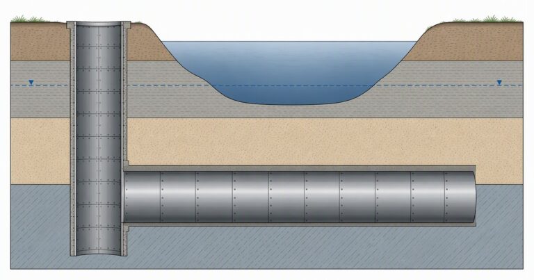
This microtunneling case study covers four steel casing crossings on the West Harris County Regional Water Authority supply project in Houston: 99.5-inch outside diameter casing jacked behind a RASA machine, out of 36-foot liner plate shafts roughly 55 feet deep, beneath roadways and waterways below the water table.
Bidding a large steel casing drive beneath a waterway turns on three questions: how the face is supported, how the shaft is built below the water table, and what the published record leaves out. This microtunneling case study covers four 99.5-inch casing crossings in Houston. The difficulty was the combination of a waterway and a road that stayed open, over a drive below the water table in lean clay with sand layers. It separates the engineering reasoning from the numbers nobody has published.
What Was the Project in This Microtunneling Case Study?
The crossings sit on the West Harris County Regional Water Authority surface water supply project near Houston, Texas. The 2022 North American Microtunneling Job Log reports two contracts: Section C1, with two crossings, and Section C2, with two further crossings totalling 604 ft. All four used 99.5-inch outside diameter steel casing pipe jacked behind the same type of machine, carrying a new water transmission main.
The pipe being installed is a water transmission main, so the casing is a sleeve rather than the finished conduit: a two-pass job. The tunneling contractor was Bradshaw Construction, working under SJ Louis Construction of Texas on Section C1 and Harper Brothers Construction on Section C2, with Freese and Nichols and Brierley Associates as engineers.
| Crossing | Length | Casing | Ground reported |
|---|---|---|---|
| Section C1, under Kieth Harrow Boulevard | 625 ft | 99.5 in. OD steel | Sand transitioning into lean clay and caliche, below the water table |
| Section C1, under Bear Creek | 380 ft | 99.5 in. OD steel | Lean clay with sand layers, below the water table |
| Section C2, first waterway crossing | 346 ft | 99.5 in. OD steel | Lean clay and sand layers, below the water table |
| Section C2, second waterway crossing | 258 ft | 99.5 in. OD steel | Lean clay and sand layers, below the water table |
Every crossing was launched and recovered from a liner plate shaft of 36 ft outside diameter and roughly 55 ft deep. A microtunneling river crossing of this length is routine. The same crossing from a 55 ft shaft below the water table is not routine, and a water transmission main under a live waterway narrows the options further.
Why 99.5-Inch Steel Casing?
Steel casing is specified where the tunnel is a structural sleeve for a separately installed carrier pipe rather than the finished conduit. That is the two-pass arrangement: the steel casing pipe must resist jacking and carry ground loads, while the carrier inside is chosen for pressure, corrosion and flow. That is the first design decision in this microtunneling case study.
The record does not state whether the casing was welded or used a restrained joint, so the detail should not be assumed. It does state the diameter: 99.5 inches outside, which places the drive where a person cannot enter. For a water transmission main of this size, that steel casing pipe is the only structure that has to survive the pipe jacking loads.
- The casing carries the jacking force and the ground; the carrier pipe carries the water.
- Casing spacers support the carrier and keep the annulus even.
- Steel tolerates bending and joint movement better than concrete jacking pipe, which helps the pipe jacking sequence.
For comparison, a 2014 paper by Bradshaw Construction describes a 42 inch ductile iron carrier jacked into a 60 inch steel casing on three casing spacers per joint. The annulus was grouted afterwards.
Why Microtunneling, Not Open Cut, Beneath Bear Creek?
Three constraints on this microtunneling river crossing point the same way. First, a trench through a creek bed involves environmental permitting, in-channel works and a construction window that a trenchless crossing avoids. Second, the 625 ft crossing under Kieth Harrow Boulevard ran under a live road, where an open trench brings traffic management costs a shaft pair does not.
Third is depth and groundwater: lean clay with sand layers, with the drives below the water table. An open cut there needs dewatering along the trench, with the settlement risk that transfers to adjacent ground, plus a discharge route.
Microtunneling replaces all three with one: the face has to be supported. Slurry face support balances slurry pressure against groundwater and earth pressure at the cutterhead. Too little pressure and the ground flows in and the surface settles; too much and the slurry escapes or heaves the surface.
What Did the Shafts Take?
The reported shaft is 36 ft in outside diameter and roughly 55 ft deep, lined with bolted steel liner plate. Those dimensions say more about the engineering than the equipment, because a microtunneling case study of this kind turns on the shaft rather than the machine. A shaft that deep below the water table has to be excavated and supported without letting water in, with a base stable enough to launch from.
- Base stability: a 55 ft excavation below the water table creates an uplift and heave problem, normally solved with a plug or by dewatering.
- Thrust wall: the shaft resists the full jacking reaction, not the average friction, so the wall and the lining are designed together.
The lining also has to keep its shape while the machine leaves, because the reaction is applied at one side and resisted by the ground on the other. Our field teams record that the thrust wall detail, not the shaft diameter, is where a microtunneling case study is won or lost.
What Did the RASA Machine Have to Do?
The published record names a RASA machine. What can be stated is the function a slurry machine performs on this drive. The machine must excavate 99.5-inch casing sections in lean clay with sand layers while holding face pressure below the water table, from a shaft 55 ft deep with the operator at the surface.
Slurry machines are described in equipment literature as suitable from silt and clay through incohesive soils to gravel and rock, because the slurry both supports the face and carries the spoil. That is why the pressure window matters on a microtunneling river crossing: the same machine must behave in stiff clay, which resists excavation, and in sand layers, which run if pressure drops.
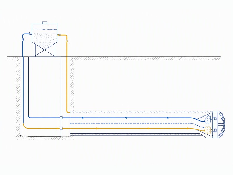
Slurry returns to the surface carrying cuttings that must be separated before the fluid is reused, so on any microtunneling river crossing the separation plant is a layout item as well as a cost item. And the machine must suit the hardest ground, because pipe jacking cannot be re-tooled halfway.
What Governs Jacking Force on a Drive Like This?
Friction governs, and friction accumulates along the entire string. Values published by the Pipe Jacking Association put frictional resistance for jacked pipe between 0.5 and 2.5 tonnes per square meter of external circumferential area, reducible to as little as 0.1 tonnes with lubrication. On a steel casing pipe of this section, that surface area is large even on a short drive.
Drive length keeps the thrust demand manageable here. At 258 to 625 ft, the crossings sit well inside the indicative jacking lengths published for this diameter band. The published indicative length for a 2.4 m internal diameter is 2,000 m, so jacking force is a design check rather than the binding constraint.
In this microtunneling case study the binding constraints lie elsewhere.
- Thrust wall capacity. The shaft must resist the reaction, and a liner plate lining transfers that load into the surrounding ground.
- Casing section and joints. A 99.5-inch casing is a stiff section, but the joint detail has to carry the jacking load without local distortion.
- Continuity. A stopped drive builds friction, and on one reported project elsewhere the jacking load rose from about 24.5 tons to over 124 tons on a single 754 ft drive.
Conclusión: settlement and water govern here, not jacking force.
What Would We Check Before Bidding a River Crossing Like This?
In our bid reviews, this is the screening sequence applied to a comparable microtunneling river crossing.
| Artículo | Question to answer | Evidence required |
|---|---|---|
| Shaft base | Will the base of a 55 ft shaft hold below the water table? | Uplift and heave check, plus a plug or dewatering plan |
| Thrust wall | Can the shaft resist calculated friction plus margin? | Reaction calculation against lining and ground capacity |
| Watertightness | How is the entry eye sealed below the water table? | Entry seal detail plus a contingency grouting plan |
| Settlement limits | What movement is allowed for the creek and the road? | Permit conditions, plus monitoring with trigger levels |
| Spoil route | Where does separated spoil and slurry water go? | Separation plant layout and disposal route |
What the Published Record Covers, and What Project Design Must Add
This is where a microtunneling case study drawn from trade reporting has to be honest: the job log entry is a project listing, not an as-built record. We have seen the gap treated as if it did not exist.
- The jacking force actually recorded on any of the four crossings.
- Measured surface settlement over the waterway and the roadway.
- Shaft dewatering volumes, or how the shaft bases were stabilized.
- Drive durations, unit costs and completion status.
None of those figures are reported here or estimated. The record establishes the configuration: 99.5-inch casing, 36 ft liner plate, roughly 55 ft deep, below the water table in lean clay with sand layers.
Scope: the record gives configuration only. Jacking force, settlement, dewatering volume and unit cost come from project documents. That is a microtunneling case study you can reason from and not one you can price.

Puntos clave
- This microtunneling case study covers four reported crossings of 99.5-inch steel casing in Houston.
- The casing is a sleeve for a separately installed water transmission main, so the work is two-pass construction.
- Every crossing was launched from a liner plate shaft of 36 ft, roughly 55 ft deep, below the water table.
- Length, not diameter, keeps jacking force manageable: friction runs at 0.5 to 2.5 tonnes per square meter, reducible to about 0.1 with lubrication.
- The governing risks are face support, shaft base stability and settlement limits.
Preguntas frecuentes
Why use steel casing instead of concrete jacking pipe?
Steel casing is specified when the tunnel is a structural sleeve for a separately installed carrier pipe rather than the finished conduit. It welds or interlocks into a continuous string that tolerates jacking, and it lets the carrier be chosen independently of the jacking pipe.
Why was microtunneling chosen instead of open cut under the creek?
Three constraints point the same way: a waterway that cannot be excavated through, a road that has to stay open, and a drive running below the water table in lean clay with sand layers. Open cut would require dewatering the crossing and rebuilding the waterway and road.
What does a liner plate shaft do on a crossing like this?
It carries the ground and the water while the drive is launched, and it provides the reaction for the thrust wall. On this project the liner plate shaft was 36 feet in outside diameter and roughly 55 feet deep, which puts the base well below the water table and makes base stability a design item.
What governs jacking force on a 99.5-inch casing drive?
Friction along the whole string. Friction in pipe jacking typically runs between 0.5 and 2.5 tonnes per square meter of external circumferential area, and lubrication can reduce it to about 0.1 tonnes. Thrust wall capacity and casing section then set the limit.
How is face support managed below the water table?
A slurry machine balances slurry pressure against groundwater and earth pressure at the face. Too little pressure and the ground flows in, causing settlement; too much and the slurry escapes or heaves the surface. The operator tunes slurry density, flow and advance rate to hold that balance.
What should be checked before bidding a river crossing like this?
Shaft base stability below the water table, thrust wall capacity against calculated friction, the face support pressure window, the casing section and joint detail, settlement limits for the waterway and the road, and the spoil handling route.
How JSW Supports Projects Like These
JSW is a pipeline engineering and construction company that executes trenchless crossings with its own crews and equipment. Our scope covers microtunneling construction, trenchless technologies, horizontal directional drilling, pipeline installation y automatic pipeline welding.
A microtunneling case study is useful only if it is read alongside your own ground. The four crossings above are a configuration, not a template: casing size and shaft depth follow from the carrier and the waterway, and everything else follows from the geotechnical report. We price the steel casing pipe, the liner plate shaft and the face support regime as one scope, so the jacking assumptions stay with those executing the drive.
- Integrated delivery: shaft, jacking, casing and carrier installation under one scope.
- Monitored drives: jacking force, guidance deviation and advance rate logged against pre-calculated limits.
- Explicit risk allocation and compliance: face support, settlement control and spoil handling priced as identified risks, under ISO 9001:2015, ISO 14001:2015 and ISO 45001:2018 certified systems.
Planning a waterway crossing and need a second opinion on the shaft and casing design? Send the alignment, casing diameter, shaft depth and geotechnical report for a free technical review. Our engineers respond with a scoped recommendation and budget range.
Sources and Standards
The project data on this page is drawn from the 2022 North American Microtunneling Job Log published by Trenchless Technology, which reports the crossings, casing size, shaft size and depth, machine, ground description and project parties. The comparative two-pass detail comes from a 2014 paper by Bradshaw Construction on a drive under the Schuylkill River in Reading, Pennsylvania. The friction and jacking figures are from published industry guidance, including work by the Pipe Jacking Association. Standards referenced in the text are ASCE/CI 36-15, EN 12889 and NASTT good practice material. No external link or citation marker is used.





































 English
  Arabic
  Russian
  Spanish
  French
  Vietnamese
  Polish
  Thai
Thai  Indonesian
  Turkish
  Portuguese