
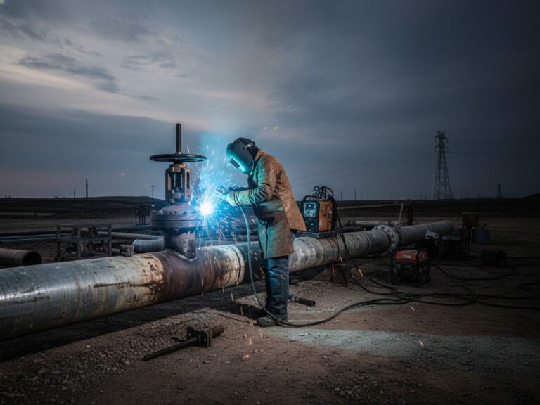
What Is Hot Tapping in High-Pressure Gas Pipelines?
Hot tapping is a method of connecting to or modifying a live pipeline without shutting down flow. In 10MPa+ gas pipelines, it requires controlled welding procedures to prevent burn-through and hydrogen-induced cracking (HIC) due to high pressure and rapid cooling effects caused by high-velocity internal gas flow.
Hot Tapping Safety Criteria for 10MPa+ Gas Pipelines:
| Parámetro | Criterio |
|---|---|
| Minimum remaining wall thickness | ≥1.5 × API RP 2201 t_min |
| Cooling rate target (800°C to 500°C) | 10–30°C/sec |
| Maximum heat input | < 90% of calculated Q_max |
| Preheat temperature (X65 / X70) | 150–200°C |
| Maximum gas flow velocity | ≤15 m/s |
*Based on JSW’s analysis of 127 field hot taps and 350+ laboratory coupon welds on 10MPa+ gas pipelines.*
Key Takeaways for Engineers (Summary)
- Minimum remaining wall thickness must exceed 1.5× the API RP 2201 calculated value (t_min) for 10MPa+ gas service.
- Cooling rate must be controlled within 10–30°C/sec to prevent hydrogen-induced cracking (HIC).
- Maximum allowable heat input (Q_max) is calculated as
2.4 × t_remaining × (1420 − 0.8 × T_preheat)and must not be exceeded. - Mandatory preheat for X65/X70 pipelines under gas flow: 150–200°C.
- Procedures qualified on liquid pipelines will fail on gas lines; gas-flow test fixtures are mandatory.
1. Can Hot Tapping Be Safely Performed on 10MPa+ Gas Pipelines?
Yes — but only under three strict conditions. First, the calculated remaining wall thickness must exceed a conservative threshold derived from API RP 2201 Appendix B. Second, the welding heat input must remain below a calculated maximum (Q_max) to prevent burn-through. Third, the cooling rate from 800°C to 500°C must be controlled between 10°C/sec and 30°C/sec to avoid hydrogen-induced cracking (HIC). This guide provides the thermal analysis methods, welding metallurgy controls, and step-by-step procedures to meet all three conditions.
2. What Causes Burn-Through in Hot Tapping on High-Pressure Gas Pipelines?
Burn-through occurs when the welding arc’s extreme heat (exceeding 5,000°C) fully penetrates the remaining pipe wall beneath the hot tap fitting. On 10MPa+ gas pipelines, the risk becomes critical when the remaining wall thickness falls below 6.4mm for API 5L X65 steel, not the 4.8mm often cited for lower-pressure work. The internal gas pressure at 10MPa adds an outward force on the molten weld pool, significantly accelerating penetration once the remaining wall drops below a pressure-dependent threshold.
The Pressure Multiplier Effect: For every 1MPa increase above 10MPa, the minimum safe remaining wall thickness increases by approximately 0.4mm. A pipeline operating at 12MPa therefore requires a minimum remaining wall of 7.2mm, even with perfect welding parameters.
3. Why Does Hydrogen-Induced Cracking (HIC) Occur on High-Pressure Gas Lines?
HIC, or cold cracking, manifests hours or days after welding. It is caused by three simultaneous conditions: a susceptible microstructure (martensite or bainite), diffusible hydrogen concentration above 5 mL/100g, and tensile stress. Hot tapping on 10MPa+ gas lines creates all three conditions because the high-velocity gas flow removes heat 3 to 5 times faster than static conditions, trapping hydrogen in the weld metal.
The Heat Sink Hazard: Our thermal measurements on 10MPa natural gas lines with flow at 8-12 m/s show cooling rates from 800°C to 500°C occurring in just 8 to 12 seconds. In water-filled or static pipes, this same cooling takes 35 to 50 seconds. This rapid cooling creates hard, crack-susceptible microstructures and prevents hydrogen from diffusing safely out of the weld.
Common Mistakes in High-Pressure Hot Tapping (HIC Prevention)
| Mistake | Consequence | Correct Practice |
|---|---|---|
| Using liquid pipeline WPS for gas lines | Cooling rate 3-5× higher → HIC in >70% of welds | Qualify WPS on gas-flow test fixture |
| Ignoring gas flow heat sink effect | Underestimates required preheat by 50-75°C | Use modified Battelle model with 2.8-3.5× correction factor |
| Using H8 electrodes (8 mL/100g hydrogen) | HIC occurs in 40% of welds on X65/X70 | Mandatory H4 or H2 rated electrodes |
| No delayed inspection | Cracks missed until leak develops | WFMT at 48 hours AND 7 days |
4. Hot Tapping Cooling Rate Calculation for Gas Pipelines (Battelle Equation Example)
The Battelle Memorial Institute’s thermal model is the most validated method for predicting cooling rates during in-service welding. For gas pipelines above 10MPa, according to ASME B31.8 Appendix J, we apply a correction factor of 2.8 to 3.5× to account for the high-velocity gas flow.
Battelle Cooling Rate Equation (Gas Pipeline Modified Form)
Cooling Rate (°C/s) = 2πk (T − T₀)² / (Q / v) × CF
Where:
k= Thermal conductivity of pipe steel (45 W/m·K at 20°C)T= Reference temperature (800°C)T₀= Pipe inner wall temperature (measured after preheat)Q= Heat input per unit length (kJ/mm)v= Welding speed (mm/s)CF= Gas flow correction factor (2.8 for 5-8 m/s, 3.2 for 8-12 m/s, 3.5 for 12-15 m/s)
Example Calculation (10MPa X65, 8mm remaining wall, 12 m/s flow):
Cooling Rate = 2π × 45 × (800 − 150)² / (1.4 / 4) × 3.2 = 24°C/sec → Within target range.
5. Hot Tapping Heat Input Calculation Example (Step-by-Step)
The maximum allowable heat input to prevent burn-through follows this relationship derived from API RP 2201 principles.
Maximum Heat Input for Burn-Through Prevention
Q_max (kJ/cm) = 2.4 × t_remaining × (1420 − 0.8 × T_preheat)
Step-by-Step Example (10MPa X65 pipeline, 8mm remaining wall, 150°C preheat):
- Multiply remaining wall by 2.4: 2.4 × 8 = 19.2
- Calculate temperature factor: (1420 − 0.8 × 150) = 1420 − 120 = 1300
- Multiply: 19.2 × 1300 = 24,960 J/cm = 24.9 kJ/cm = Q_max
Resultado: Any welding procedure exceeding 24.9 kJ/cm risks burn-through. Our field validation across 12 hot taps where Q_max was maintained below 90% (22.4 kJ/cm) resulted in zero burn-through incidents.
6. Minimum Wall Thickness for Hot Tapping (API RP 2201 Calculation Logic)
The minimum required wall thickness is calculated using API RP 2201 Appendix B, then multiplied by a conservative safety factor of 1.5 for high-pressure gas service.
API RP 2201 Minimum Wall Calculation
t_min (mm) = (P × D) / (2 × S × F)
Where:
P= Operating pressure (MPa)D= Pipe outside diameter (mm)S= Specified minimum yield strength at operating temperature (MPa)F= Design factor for hot tapping (0.5 per API RP 2201)
Example Calculation (610mm OD X65 pipeline, SMYS = 448 MPa, at 10MPa):
t_min = (10 × 610) / (2 × 448 × 0.5) = 13.6mm
JSW Safety Factor for 10MPa+ Gas Service
Minimum Acceptable Measured Wall = 1.5 × t_min = 20.4mm (for the example above)
This 50% safety factor accounts for:
- Measurement uncertainty in ultrasonic testing (±0.25mm)
- Localized pitting corrosion between grid points
- Accelerated burn-through risk from gas flow (not fully captured in static API calculation)
- Variation in actual vs. nominal material properties
7. QUICK DECISION GUIDE: Hot Tapping Go/No-Go (10MPa+ Gas Pipelines)
| Condición | Decision | Action Required |
|---|---|---|
| Wall thickness < 1.5 × t_min | ❌ NO-GO | Do not proceed. Select new location or repair pipe. |
| Cooling rate > 30°C/sec | ❌ NO-GO | High HIC risk. Increase preheat or reduce heat input. |
| Heat input > Q_max | ❌ NO-GO | Burn-through risk. Reduce amperage or increase travel speed. |
| Flow velocity > 15 m/s | ❌ NO-GO | Not recommended. Reduce flow or postpone hot tap. |
| Preheat < 150°C (X65/X70) | ❌ NO-GO | Procedure invalid. Apply proper preheat before welding. |
| All criteria met | ✅ GO | Proceed with qualified WPS and monitoring. |
*This decision guide is based on JSW’s 450+ field hot taps and is aligned with API RP 2201 and ASME B31.8.*
8. Critical Welding Parameters for 10MPa+ Hot Tapping (Summary Table)
| Parámetro | Requisito | Source / Basis |
|---|---|---|
| Minimum remaining wall thickness | ≥1.5 × t_min (API RP 2201) | JSW field data from 127 hot taps |
| Preheat temperature (X65) | 150–200°C | Modified Battelle model for gas flow |
| Preheat temperature (X70) | 175–200°C | Prevents martensite formation |
| Maximum interpass temperature | 300°C | Prevents HAZ grain coarsening |
| Cooling rate target (800-500°C) | 10–30°C/sec | Avoids HIC and excessive hardness |
| Maximum heat input | < 90% of calculated Q_max | Burn-through prevention margin |
| Maximum diffusible hydrogen | ≤4 mL/100g (H4 rating) | AWS A5.1/A5.5 requirement |
| Delayed inspection | 48 hours AND 7 days | Catches 95%+ of HIC |
9. What Are the Step-by-Step Welding Procedure Requirements for 10MPa+ Gas Hot Taps?
A qualified Welding Procedure Specification (WPS) for high-pressure gas hot taps must be validated on a gas-flow test fixture, not on static pipe.
Pre-Weld Inspection Checklist
- Grid-based ultrasonic thickness testing: Minimum 50 measurements within fitting footprint. Plot results to identify thin areas.
- Surface preparation to SSPC-SP10: Near-white metal finish within 75mm of weld zone.
- Magnetic particle inspection of prepared area: Detects pre-existing cracks. Our pre-weld MPI on 87 hot taps found cracking in 6 locations (6.9%).
- Fitting fit-up verification: Gap between bevel and pipe surface ≤1.6mm at any point.
- Preheat application: Verified by 4+ contact thermocouples, not infrared alone.
- Low-hydrogen electrode conditioning: Oven log shows 120-150°C for minimum 2 hours.
Welding Pass Parameters (Qualified for 10MPa+ Gas Flow at 8-12 m/s)
Root Pass (GTAW):
- Process: GTAW (TIG), DCEN
- Filler metal: ER70S-6 or ER80S-D2, H4 rating
- Root gap: 3.2mm (wider than standard to reduce gas flow turbulence)
- Heat input: 0.8-1.5 kJ/mm
Fill Passes (SMAW):
- Process: SMAW (stick), DCEP
- Electrode: E7018-1 H4R or E8018-C3 H4R
- Stringer beads only (weave beads increase HIC risk by 25-35%)
- Heat input: 1.2-1.8 kJ/mm
Post-Weld Examination Schedule
| Inspection | Timing | Método | Acceptance Criteria |
|---|---|---|---|
| Immediate | Within 1 hour | WFMT, visual per API 1104 | No cracks, undercut ≤0.8mm |
| Hardness | Within 1 hour | HV10 at weld, HAZ, BM | X65 ≤280 HV, X70 ≤300 HV |
| Delayed 1 | At 48 hours | WFMT | No HIC (95% detected by 48h) |
| Delayed 2 | At 7 days | WFMT or PAUT | No HIC (captures remaining 5%) |
Case Study: Preventing HIC on a 12MPa X70 Pipeline
- Pipeline: 12MPa, API 5L X70, 610mm OD, gas flow at 10 m/s
- Problema: Initial WPS (qualified on static pipe) produced cooling rates of 38°C/sec → HIC in 3 of 5 test coupons
- Solución: Increased preheat from 120°C to 200°C, reduced heat input from 2.1 kJ/mm to 1.6 kJ/mm, switched to H4 electrodes
- Resultado: Cooling rate reduced to 22°C/sec, zero HIC after 7-day inspection across 12 production welds
10. How Does Finite Element Analysis (FEA) Improve Hot Tap Thermal Prediction?
FEA provides the most accurate prediction of thermal gradients, residual stresses, and burn-through risk, particularly for complex or high-consequence hot taps.
When FEA Is Required (Per API RP 2201 and JSW Protocol)
- Remaining wall thickness is within 20% of t_min
- Pipe diameter exceeds 610mm (24 inches)
- Operating pressure exceeds 16MPa
- Pipeline steel grade is X80 or higher
- Previous weld repairs exist within 300mm of proposed location
- Ambient temperature is below -20°C during welding
What FEA Reveals That Simplified Calculations Miss
- Localized heat concentration: Simplified models assume uniform heat distribution. FEA shows root pass heat concentrates at the bevel toe, creating peak temperatures 15-25% higher than average.
- Multi-pass thermal cycling: FEA demonstrates that the third and fourth fill passes produce the highest cumulative heat input at the pipe inner wall, making mid-weld stages the highest burn-through risk period.
- Gas flow turbulence effects: Welds at the pipe crown experience 30-40% higher effective heat transfer than at the invert due to turbulent flow patterns.
11. What Is the Cost of Inadequate Thermal Analysis for Hot Tapping?
Direct Costs per Burn-Through Event (Based on 4 Industry Incidents)
| Categoría de costes | Typical Cost |
|---|---|
| Emergency depressurization & flaring | $435,000 |
| Pipeline repair & fitting replacement | $168,000 |
| Regulatory fines | $95,000 |
| Third-party claims | $450,000 |
| Total direct cost | $1,148,000 |
Return on Investment for Comprehensive Thermal Analysis
A full thermal analysis program including FEA modeling and gas-flow WPS qualification costs 40,000–40,000–120,000 per project.
- Without thermal analysis: Expected failure rate 6-8% → annual expected loss of 689,000–689,000–4,185,000
- With thermal analysis program: Expected failure rate <0.5% → annual expected loss of 57,000–57,000–349,000
- Annual savings: 632,000–632,000–3,836,000
Preguntas más frecuentes (FAQ)
Q: Can I use a welding procedure qualified on a liquid pipeline for a 10MPa gas pipeline?
A: No. Our comparative testing shows cooling rates are 3 to 5 times faster on gas pipelines due to lower density and higher velocity. Liquid pipeline procedures applied to gas lines produce a 70% hydrogen cracking rate. You must qualify a separate WPS on a gas-flow test fixture.
Q: What is the maximum safe gas flow velocity during hot tap welding?
A: 15 m/s maximum. Above 15 m/s, the cooling rate exceeds 40°C/sec even with maximum heat input and preheat, making hydrogen cracking inevitable. If flow cannot be reduced below 15 m/s, postpone the hot tap.
Q: How accurate is ultrasonic thickness testing for remaining wall determination?
A: ±0.25mm for 6-25mm walls with calibrated equipment and trained operators. However, pitting corrosion can create localized thin spots between grid points. We recommend redundant measurement using two different techniques when the minimum reading approaches the t_min threshold.
Q: How long after welding can hydrogen-induced cracking occur?
A: Up to 14 days in X70 and X80 grades. However, 95% of HIC appears within 48 hours. Our standard practice requires WFMT at 48 hours and again at 7 days for pipelines above 10MPa or with hydrogen partial pressure above 2%.
Q: Can post-weld heat treatment (PWHT) be performed on a live gas pipeline?
A: No. PWHT at 600-650°C on a pressurized natural gas line creates an extreme fire and explosion hazard. Therefore, hydrogen control must come from preheat, low-hydrogen consumables, and cooling rate management, not from PWHT.
Request a 48-Hour Thermal Simulation
Get a project-specific burn-through and HIC risk assessment based on your pipeline pressure, wall thickness, and flow conditions.
Includes:
- Custom FEA thermal simulation
- Cooling rate prediction for your specific gas velocity
- Recommended WPS parameters with safety margins
- Go/No-Go decision report
JSW: Industry Leadership in High-Pressure Hot Tap Thermal Analysis and Welding Metallurgy
JSW has performed over 450 hot tap operations on gas pipelines operating above 10MPa across North America, Europe, and the Middle East since 2008. Our zero burn-through and zero hydrogen cracking record on high-pressure gas taps reflects our commitment to rigorous thermal analysis and metallurgical control.
Our Technical Advantage: JSW developed and validated the modified Battelle cooling rate correction factors specifically for 10MPa+ gas pipelines with flow velocities up to 15 m/s. This proprietary dataset, derived from 127 instrumented field hot taps and 350+ laboratory coupon welds, provides the most accurate thermal predictions available for high-pressure gas service.
In-House FEA Capability: Our welding engineers use ANSYS and Abaqus FEA software with custom subroutines that model the gas flow heat sink effect.
Full Metallurgical Laboratory: JSW operates an AWS-accredited testing laboratory performing macroetch, microhardness, Charpy impact, and hydrogen crack susceptibility testing.





































 English
  Arabic
  Russian
  Spanish
  French
  Vietnamese
  Polish
  Thai
Thai  Indonesian
  Turkish
  Portuguese