
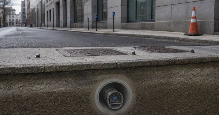
Microtunneling settlement is ground movement caused by the drive, and it is controlled by limiting volume loss: face loss and over-excavation, the overcut annulus, slurry or lubricant loss into the ground, joint drag, shaft-related loss, and groundwater drawdown with consolidation all contribute, and they are managed with face pressure control, excavated volume accounting, lubrication quality and prompt annulus grouting. Publishing practice commonly caps surface movement at 5 mm beneath existing services including roads and 10 mm beneath undeveloped land, and both values have to be confirmed for the actual assets on the drive.
This guide sets out how settlement is predicted with the Gaussian settlement trough and volume loss, the published limit values that specifications commonly apply, what a monitoring plan and a dilapidation baseline should contain, and the mitigation measures and the stop-and-report protocol for when a limit is approached. Every value here is an input to project-specific design, not a substitute for it.
What Causes Settlement in Microtunneling?
Settlement is the ground closing the gap that the machine and the pipe leave behind: each mechanism leaves a different signature at the surface, so the first design step is to identify which one governs the drive rather than to select a remedy.
| Mecanismo | How it develops | Usual control |
|---|---|---|
| Face loss and over-excavation | Soil enters the machine faster than the design volume because face pressure is too low | Face pressure control and excavated volume accounting |
| Overcut annulus | The machine cuts beyond the pipe outside diameter; the ring of ground around the pipe closes in | Annulus grouting and lubrication quality |
| Slurry or lubricant loss | Support fluid escapes into permeable or fissured ground and the annulus pressure drops | Density and filtration control, and grouting |
| Joint drag | Pipes drag on the surrounding ground as the train advances | Lubrication quality and controlled advance |
| Shaft-related loss | The shaft itself changes stress and groundwater conditions around it | Shaft design and sealed or cut-off construction |
| Groundwater drawdown and consolidation | Dewatering or drainage lowers the water table and soft ground consolidates | Groundwater control design and settlement monitoring |
In our design reviews, the discussion usually narrows quickly to two mechanisms: face loss, which is fast and intense, and drawdown-induced consolidation, which is slower and wider. On drives we have supported, the wider, slower movement has often been the one that affected nearby services, because it was not tied to an obvious moment in the drive and was therefore easy to miss without a monitoring plan in place.
The way microtunneling settlement develops is rarely uniform along a drive. Ground that is stiff and dry at the launch can be soft and wet beneath a road crossing, so the mechanism that dominates changes as the machine advances, and the monitoring plan has to reflect that rather than assume a single behaviour. Two mechanisms that look similar at the surface can have very different causes and very different fixes.
How Is Microtunneling Settlement Predicted?
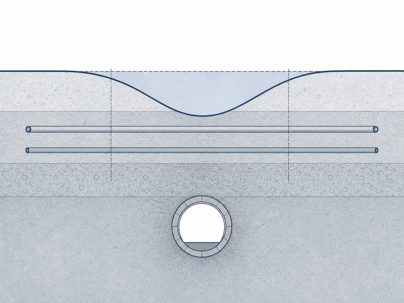
Surface settlement from tunnelling is commonly modelled as a Gaussian settlement trough, an approach attributed to Peck and later related to depth by O’Reilly and New, in which the proportion of ground lost is the primary driver of maximum settlement. The prediction is not a guarantee of the outcome, but it gives the shape, the width and the depth of the zone that the monitoring plan has to cover.
The trough width coefficient, usually written as i, varies approximately linearly with depth according to the relationship described by O’Reilly and New in 1982, so a deeper drive produces a wider trough even at the same volume loss. That is why a plan built only on surface readings from a shallow drive can under-cover a deeper one, and why the predicted trough rather than a standard instrument spacing should set the layout.
Volume loss is the proportion of excavated tunnel volume that is not replaced. Where control is good, a figure of about 1% is commonly reported; that proportion is read as a control indicator, and a UK level-crossing microtunneling case study reported the same figure. At the other end, a documented sewer pipe jacking and microtunneling case study in Ipoh, Perak reported volume loss ranging from 0.80% to 12.68%, corresponding to the lowest and highest surface settlements measured. That range is a warning about sensitivity, not a target, and it should be read as case-specific.
Prediction is an estimate, not a measurement, so microtunneling settlement has to be reviewed as the drive progresses. The prediction becomes a control tool only when it is compared against the readings as the drive advances: the model sets where to look, and the readings confirm or contradict it.
What Settlement Limits Should a Specification Set?
If the question is how much surface movement a microtunneling drive beneath a live road may be allowed to cause, the published starting point is a utility specification (Unitywater Pr9787) that caps surface movement, either up or down, at 5 mm beneath existing services including roads and 10 mm beneath undeveloped land. Those are working limits for a typical urban drive, and the governing value for a specific asset has to be confirmed by a competent engineer.
| Asset or area | Commonly published movement limit |
|---|---|
| Existing services, including roads | Surface movement not exceeding 5 mm, up or down |
| Undeveloped land | Surface movement not exceeding 10 mm, up or down |
| Dilapidation and monitoring coverage around a shaft | At least 3 times the shaft depth, measured radially from the shaft perimeter |
| Dilapidation and monitoring coverage along the drive | At least 2 times the depth to invert, measured from the pipe centerline |
The coverage rules matter as much as the numbers. A limit of 5 mm is only useful if the instruments that could detect it are installed over the zone of influence, and the zone is defined by geometry, not by convenience. Any area inside the settlement trough or the wider zone of influence is included as well, and a road or rail authority will typically set its own limits on top of these.
For any drive, the limits that apply to microtunneling settlement are set asset by asset, and the party who owns the risk reads them differently: a municipal sewer owner asks what the buried asset can tolerate, an EPC bidder asks what the contract will measure and at what trigger, and a third-party monitoring consultant asks which instrument proves it. A buried gas main, a masonry facade and an open field do not tolerate the same movement. Those two figures – 5 mm beneath existing services including roads and 10 mm beneath undeveloped land – are a starting point for setting a settlement limit per asset.
What Should a Settlement Monitoring Plan Contain?
If the question is how much settlement a microtunneling drive beneath a live road should be allowed to cause before the work stops, a settlement monitoring plan starts from the predicted settlement trough and covers the whole zone of influence, with fixed benchmarks outside it. The instrument layout, the reading frequency and the reporting route all follow from that prediction rather than from a standard spacing.
- Instrument layout from the predicted trough. Surface points, buried extensometers or inclinometers are placed where the prediction shows movement, densest over the assets with the tightest limits.
- Benchmarks outside the zone of influence. Reference points are placed beyond the zone of influence so that the readings measure the drive and not the benchmark moving with it.
- Daily reporting. Readings are reported at a frequency matched to the risk and to the advance rate, with a defined trigger level that requires action.
- Dilapidation reports before and after. The condition of roads, buildings and services is recorded before the drive and again afterwards, so pre-existing defects are documented separately from any the drive causes.
- Authority requirements. Where the drive crosses or runs near a road or rail corridor, the authority’s own monitoring, access and reporting requirements are built into the plan from the start.
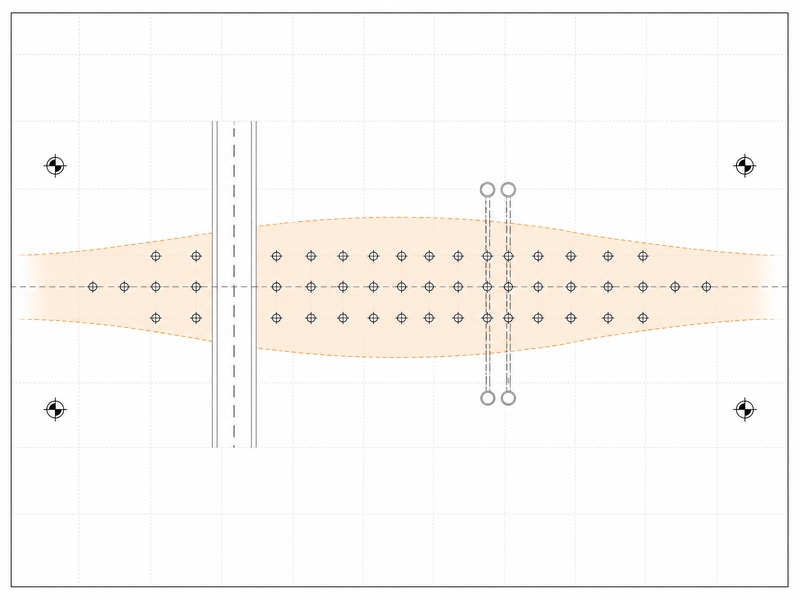
Instrument layout is also where the plan and the construction method meet: if the prediction shows movement beneath a tight asset, either the instruments get denser over that asset or the mitigation gets stronger before the drive reaches it. That decision is easier to make at design stage than at the face, which is why microtunneling settlement planning is reviewed together with the tunnel alignment rather than after it.
How Do You Mitigate Settlement During a Drive?
Mitigation is a set of live controls on the drive rather than a single fix applied at the end: face pressure control, excavated volume accounting, advance rate, lubrication quality and prompt annulus grouting, with compensation grouting and ground improvement reserved for high-risk assets. The levers below are used together, and the choice of which to combine depends on the mechanism that dominates and on the assets above.
| Measure | What it controls | Used when |
|---|---|---|
| Face pressure control | Face loss and over-excavation at the cutter head | All drives; the primary lever in soft ground |
| Excavated volume against theoretical volume | Detects over-excavation before settlement shows at the surface | As a continuous check on every drive |
| Advance rate management | Limits time-dependent loss and lets the face stabilise | Where ground is sensitive or time effects are expected |
| Lubrication quality | Joint drag and the annulus pressure that keeps the ground away from the pipe | Long drives and any drive with high friction |
| Immediate annulus grouting | Closes the drainage path and limits long-term settlement and erosion | After each advance where voids would otherwise remain |
| Compensation grouting | Offsets predicted movement beneath a specific asset | Where a tight limit sits over a sensitive structure |
| Ground improvement and sealed or cut-off shafts | Reduces loss at the shaft and improves the ground around it | Poor ground, high water table or tight asset limits |
Annulus grouting deserves particular care, because it is also a source of risk: a grout design must prevent flotation of the pipe, prevent buckling or overloading, and prevent ground surface heave or damage to adjacent assets. Over-pressure grouting can lift the surface as surely as under-grouting lets it drop, which is why grout pressure and volume are monitored rather than assumed. The Pipe Jacking Association notes that intermediate jacking stations redistribute force and reduce load on the shaft, and that a headwall and seal assembly below the water table retains annular lubricant, which supports the same settlement control objective.
The order in which these measures are brought in also matters. Face pressure and volume accounting are set from the first advance, lubrication and grouting follow the drive, and compensation grouting or ground improvement are prepared in advance for the assets that need them. Together these levers are the live control system for microtunneling settlement, and they are adjusted against the readings rather than set once at the start of the drive.
When Should Work Stop and Be Reported?
A settlement control plan needs a stop-and-report protocol, so that a limit being approached triggers a defined response rather than a judgement call at the face.
- Trigger levels. A watch level, an action level and a limit are defined against the predicted trough, with the response to each stated in advance.
- Immediate action. When a limit is approached or exceeded, the advance is adjusted or paused, the cause is reviewed, and the mitigation is changed before normal advance resumes.
- Reporting. Readings, the action taken and the reason are recorded and reported, so the response is auditable and lessons carry into the next drive.
The protocol is what turns readings into a decision: the trigger, the person who acts on it and the record required are all agreed before the drive starts. We have seen plans that recorded movement accurately and still missed the moment to act, because no one had decided in advance what the readings would trigger.
What Are Dilapidation Reports and Why Do They Matter?
A dilapidation report is a recorded survey of asset condition before and after the works, and it protects both the owner and the contractor by separating pre-existing defects from new ones. A recorded dilapidation baseline is what lets a crack found after a drive be judged on evidence: defects present before the works are separated from those the drive caused.
Coverage commonly extends at least 3 times the shaft depth radially from the shaft perimeter and 2 times the depth to invert from the pipe centerline, plus any area within the settlement trough or zone of influence. Reports are usually prepared before construction and again after it, and where a road or rail authority is involved its own requirements govern the format, the timing and the access arrangements.
Our field teams record the condition of every asset inside the zone of influence before the first monitoring reading is taken, so the baseline and the instrument layout are set together.
The overcut and lubrication controls that sit behind this settlement picture are treated in our overcut, lubrication and settlement guide, the drawdown contribution in our microtunneling groundwater control guide, and the shaft geometry behind the coverage rule in our shaft sizing guide.
Preguntas frecuentes
What causes settlement in microtunneling?
Settlement comes from volume loss around the drive. The main contributors are face loss and over-excavation, the overcut annulus around the pipe, slurry or lubricant loss into permeable ground, joint drag, shaft-related loss, and groundwater drawdown with the consolidation that follows.
How much settlement is acceptable in microtunneling?
Published utility specifications commonly allow surface movement up or down of no more than 5 mm beneath existing services including roads, and 10 mm beneath undeveloped land, unless otherwise approved. Those figures are starting limits and the governing value is set for the actual assets and confirmed by a competent engineer for the drive.
What is volume loss in microtunneling?
Volume loss is the proportion of the excavated tunnel volume that is not replaced by the pipe and the ground moving back in, and it is the primary driver of maximum settlement. Volume loss of about 1% is reported where control is good, while a documented sewer pipe jacking and microtunneling case study reported volume loss ranging from 0.80% to 12.68%.
How is microtunneling settlement monitored?
Monitoring starts from the predicted trough. Instruments are laid out over the zone of influence, benchmarks are placed outside it, readings are reported daily, and pre- and post-construction dilapidation reports record the condition of assets before and after the drive. Road and rail authorities usually impose their own requirements.
How can settlement be reduced during a microtunneling drive?
Settlement is reduced by controlling face pressure, comparing excavated volume against theoretical volume, managing advance rate, keeping lubrication quality high, and grouting the annulus promptly. Compensation grouting, ground improvement and cut-off or sealed shafts are further options where the risk is high.
What is a dilapidation report?
A dilapidation report is a recorded survey of the condition of buildings, roads, services and other assets before and after construction, so that pre-existing defects are separated from any the works cause. Coverage commonly extends at least 3 times the shaft depth radially from the shaft perimeter and 2 times the tunnel depth from the pipe centerline.
Puntos clave
- Microtunneling settlement is driven by volume loss, and the main mechanisms are face loss, the overcut annulus, fluid loss, joint drag, shaft-related loss and drawdown-induced consolidation.
- Prediction uses the Gaussian settlement trough, with the trough width coefficient rising approximately linearly with depth; volume loss sets the maximum settlement.
- Published limits commonly cap surface movement at 5 mm beneath existing services including roads and 10 mm beneath undeveloped land, with monitoring coverage of at least 3 times the shaft depth and 2 times the tunnel depth; for any drive the tightest asset limit governs acceptance.
- Monitoring starts from the predicted trough, with benchmarks outside the zone of influence, daily reporting and pre- and post-construction dilapidation reports.
- The point at which work stops is decided before the drive: a watch level, an action level and a limit, each tied to a named person and a written record.
- Mitigation combines face pressure control, volume accounting, advance rate, lubrication quality and prompt annulus grouting, with compensation grouting and ground improvement for high-risk assets.
- Every limit and range on this page is an input to project-specific design and must be confirmed by a competent engineer for the actual drive.
How JSW Supports Settlement Control in Microtunneling
JSW is a pipeline engineering and construction company that executes trenchless drives with its own crews and equipment. Our scope covers microtunneling construction, where the drive and its monitoring are executed, together with the wider trenchless technologies portfolio where a crossing needs a different method. Before and during a drive we provide pipeline inspection service, and afterwards pipeline repair services y external pipeline repair, so monitoring and any subsequent repair sit under one responsibility.
Because the design basis and the construction team sit together, microtunneling settlement risk is reviewed against the equipment and crews that will execute the drive, and risk items are priced separately with their triggering conditions stated. Monitoring data, grouting records and dilapidation surveys are archived so that the outcome can be audited during construction and afterwards.
- Integrated delivery: settlement prediction, monitoring plan, drive execution and annulus grouting under one scope, removing the handover between designer and constructor.
- Auditable engineering: the prediction, the assumed inputs and the trigger levels are recorded, so a reviewer can trace each limit to the asset and the analysis behind it.
- Risk-explicit pricing: drawdown, fluid loss and asset-sensitivity risks are identified and priced against defined triggers rather than bundled into one figure.
- Urban and crossing experience: drives beneath services, roads and rail with monitoring, access and reinstatement inside the same delivery.
Need a settlement monitoring and mitigation plan for a microtunneling drive? Send the alignment and invert levels, the ground investigation, the assets above the route and the limits that apply. Our engineers return a scoped settlement review, a monitoring approach, the watch, action and limit levels we expect to govern, and a budget range.





































 English
  Arabic
  Russian
  Spanish
  French
  Vietnamese
  Polish
  Thai
Thai  Indonesian
  Turkish
  Portuguese