

An HDD pullback load (horizontal directional drilling pullback load) analysis is the set of checks that shows a pipe can be installed by horizontal directional drilling without exceeding its allowable stress, without collapsing, and without overloading the rig. This guide sets out the components that make up the total load, how ASTM F1962 frames installation loads, and the checks that should be complete before the pull starts: tensile stress, combined tension and bending, buckling, collapse, ovality, buoyancy control, pull speed and rig capacity margin. It is a check set and an acceptance framework, not a table of values to copy.
What Makes Up the Total HDD Pullback Load?
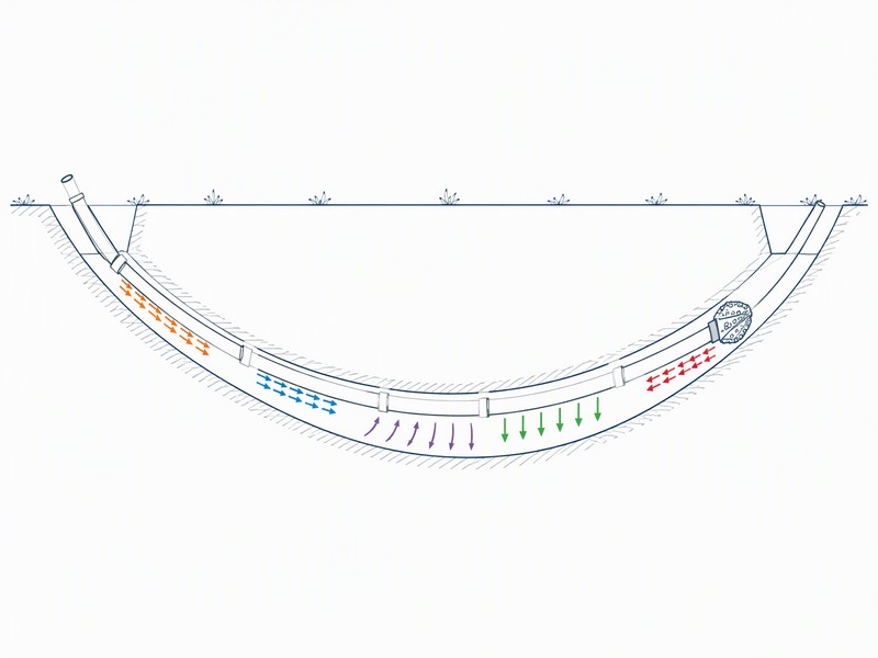
The total HDD pullback load is a sum of physical effects that have to be estimated one by one, because each component responds to a different variable.
The components below are the terms in that sum; the shares are planning aids rather than fixed proportions, and the split must be calculated for the pipe, the profile and the ground.
| Load component | What drives it | Typical share of the total (illustrative) |
|---|---|---|
| Bore friction | Net normal load of the pipe against the bore wall, times the friction coefficient, over the contact length | Often the largest single term, commonly about half to two thirds of the total; a typical planning range, not a measured figure |
| Fluid drag | Mud viscosity, flow rate, annulus clearance and pull speed | Modest, but grows with length and with heavy mud |
| Curvature and capstan effect (the amplification of running tension as the string wraps through a curve) | Wrap angle through the bends multiplied by the friction coefficient along the curve | Typically amplifies the running tension by 5 to 15% at moderate wrap angles; a planning range, not a measured figure |
| Weight and buoyancy | Pipe weight, contents, displaced volume of the bore fluid and the profile slope | Can add to or subtract from the load. If buoyancy is not controlled, it can dominate |
| Reamer and swab effects | Reamer type and size, cuttings load ahead of the reamer, and the pipe acting as a swab | Usually a smaller term, but it rises sharply when the hole is not clean |
| Surge at start and stop | Acceleration of the string, and rapid changes in pull speed | Short-duration peak that can govern the tension record |
These shares are a planning aid rather than a design value; during the pull, log tension and torque against pull speed so the calculated split can be checked against what the rig actually sees. On crossings we have supported, the difference between the estimated and recorded load has usually turned on hole cleaning and on how well the pipe buoyancy was managed, not on the friction coefficient that was assumed.
How Does ASTM F1962 Treat Installation Loads?
ASTM F1962 is the standard guide for the use of maxi-horizontal directional drilling to place polyethylene pipe and conduit under obstacles, including river crossings, and it provides a calculation framework for the installation case rather than a set of ready answers: bore geometry, the loads applied during pullback, and the resulting stress in the pipe. Current editions are F1962-22 and F1962-25, and an active revision, work item WK93768, proposes, among other changes, an 8% deflection limit for both pressurised and non-pressurised pipe across all DR ratings. Confirm the edition in force at the time of your design, and treat the proposed 8% limit as a proposal until it is published, not as a current acceptance value.
ASCE Manual of Practice 108, Pipeline Design for Installation by Horizontal Directional Drilling, is the pipeline-design companion; together they frame the question this article answers: once the HDD pullback load has been estimated, what must be checked before the pipe is committed to the bore?
Which Design Checks Must Be Completed Before Pullback?
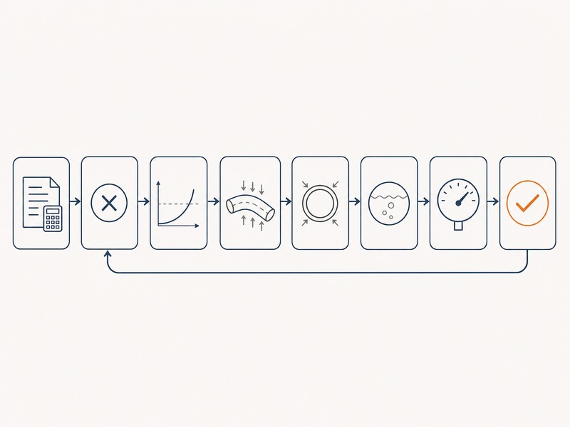
A single HDD pullback load estimate proves nothing on its own; what an owner and a designer need is an acceptance framework, not one number. The check set below follows the installation-design intent of the standards named above and is the one we work through in our design reviews before a pull is released.
Check group 1: tension in the pipe
This group answers whether the pipe itself can carry the pull. The first check compares calculated installation tension, divided by the pipe wall area, against the allowable tensile stress for the material and the design case. The second adds the bending stress generated as the pipe follows the curve of the bore, because combined tension and bending governs at the bend radius, not tension alone.
Check group 2: compression during backreaming and push
This group answers whether the pipe risks buckling or collapse. Where the string is advanced rather than pulled, or where the leading end loads up against the reamer, the pipe is in compression and buckling becomes possible. The collapse check compares the net external pressure acting on the pipe during the pull with its collapse resistance, because a thin-wall pipe under external head can collapse before it ever reaches its tensile limit.
Check group 3: geometry, ovality and buoyancy
This group answers whether the installed pipe keeps its shape and position. Installation can leave the pipe out of round, so post-installation ovality and deflection are checked against the limit in force, including the 8% deflection limit proposed in the current revision work. Buoyancy sits in this group, because whether the pipe floats, sinks or stays neutral inside a fluid-filled bore drives both the friction term and the pipe’s position in the hole.
Check group 4: pull operation and equipment
This group answers whether the pull stays inside the equipment’s limits. Pull speed and surge behaviour belong in the design, not only in the field procedure, because a rapid start raises the peak tension. The last check is rig capacity margin: the design pullback load compared with the rig’s rated pullback, with margin held back for the conditions that will actually be found.
The table below is the acceptance framework: what each check compares, the basis it is compared against, and the action when the margin is not there; it is a checklist for the design review, not a set of fixed limits.
| Check | Acceptance basis | Action if exceeded |
|---|---|---|
| Tensile stress versus allowable | Installation tension divided by pipe wall area, with the project safety factor applied, against the allowable axial stress | Increase wall thickness or change DR, shorten the pull, reduce friction, or add intermediate handling |
| Combined tension plus bending at curvature | Axial stress plus bending stress at the minimum working bend radius against the allowable | Flatten the profile, increase the bend radius, or select a pipe better suited to the curvature |
| Buckling during backreaming or push | Compressive load at the leading end against the critical buckling load for the unsupported length | Replace push with pull where possible, reduce unsupported length, or use a casing |
| Net external pressure and collapse during pull | External head minus internal pressure against the pipe collapse resistance | Fill or pressurise the pipe, reduce the installation depth or the drilling fluid head |
| Ovality and deflection limits | Post-installation ovality or deflection against the acceptance limit in force, including the proposed 8% limit | Reduce curvature or pull load, or change DR and wall thickness |
| Buoyancy and pipe filling | Net buoyant condition and pipe position in the fluid-filled bore | Fill, ballast or otherwise control buoyancy, and adjust the mud density |
| Pull speed and surge | Recorded tension against the planned speed ramp, with no unexplained peaks | Ramp speed in a controlled manner and monitor tension continuously |
| Rig capacity margin | Design pullback load against the rig rated pullback, with the project margin held | Select a larger rig, reduce the load, or split the crossing |
Each check should be signed off against a named basis before the pull is released.
None of these numbers can be lifted from a table. They are inputs to project-specific design, and the loads, factors and example on this page have to be confirmed by a competent engineer for the actual crossing. A rule of thumb is never a substitute for calculation.
Worked Example: An Illustrative HDD Pullback Load Calculation
The example below is illustrative only. It shows the arithmetic rather than a design, and every input is assumed and rounded for clarity. No field or project data is claimed anywhere in this section; the inputs are assumed and the outputs are arithmetic results only.
Assumed inputs:
- Crossing length L = 900 m
- Product pipe: HDPE, outside diameter 400 mm, DR 17, wall about 23.5 mm
- Effective net normal load after buoyancy control, w = 0.10 kN/m
- Friction coefficient along the bore, mu = 0.30
- Fluid drag allowance = 12.0 kN
- Reamer and swab allowance = 10.0 kN
- Total wrap angle through the curves, theta = 0.40 rad
- Safety factor on the estimated load = 1.5
The check runs in six steps: bore friction; running tension; curvature amplification by the capstan effect; the design pullback load; the pipe stress check; and the margin on the rig.
- Step 1, bore friction (illustrative): F_friction = mu x w x L = 0.30 x 0.10 kN/m x 900 m = 27.0 kN.
- Step 2, running tension before the curves (illustrative): T_running = 27.0 + 12.0 + 10.0 = 49.0 kN.
- Step 3, curvature amplification from the capstan effect (illustrative), using the relationship e raised to the power of (mu x theta): multiplier = e^0.12 = 1.1275, so T_estimated = 49.0 x 1.1275 = 55.2 kN.
- Step 4, design pullback load (illustrative): T_design = 55.25 x 1.5 = 82.9 kN.
- Step 5, pipe stress check (illustrative): wall area A = 3.1416 / 4 x (0.400^2 – 0.353^2) = 0.02780 m^2, so stress = 82.9 kN / 0.02780 m^2 = 2.98 MPa. At this load, the axial stress is a small fraction of the allowable tensile stress for the material, so tension is not the governing check in this illustrative case.
- Step 6, rig capacity margin (illustrative): with a rig rated at 130 kN of pullback, margin = 130 / 82.9 = 1.57, which is roughly 57% spare.
These numbers illustrate the method rather than a design, and the governing values must come from the survey profile, the pipe data sheet and the fluid programme for the actual crossing.
Hold the other inputs and double the wrap angle to 0.60 rad: the multiplier becomes 1.1972 and the design load 88.0 kN, about 6% above the first case, so geometry alone moved the design load.
The design load of 82.9 kN is the number the checks work to, not the rig’s rating. And the margin on the rig does not replace the safety factor on the load; they are two separate controls, and both have to hold.
Where Pullback Load Analysis Usually Goes Wrong
The failures that surface in this check set are usually framing errors, and most of them are visible before the pull when the numbers are read critically. They are the assumptions and the omissions that surround the calculation rather than arithmetic mistakes. Our field teams record tension against pull speed on every pull, and the pattern repeats.
- Treating the rig’s maximum pullback as the design limit. The rated pullback is an equipment figure. The design limit is the allowable stress in the pipe, and the rig is chosen to sit inside that, with margin. Working to the rig maximum removes the margin that hole condition and pull-speed variation will consume.
- Dropping the safety factor, or applying it to the wrong quantity. Published practice commonly quotes a factor in the region of 1.5 to 2.0 on the estimated load as typical, and the value is a project decision. Applying it to the rig figure instead of the load confuses two different controls.
- Assuming one friction coefficient for the whole bore. Sand, clay and rock respond differently, and the hole condition changes as reaming proceeds. A single value for 900 m of mixed ground is an average that never happened anywhere.
- Ignoring the capstan effect over several bends. The effect compounds where the string wraps more than once, so a profile with two moderate curves can carry more amplification than one sharp curve.
- Leaving buoyancy out of the design. Whether the pipe floats, sinks or sits neutral changes the normal load, the friction term and the pipe’s position in the hole. It is a design variable, not a field preference.
- Assuming tension is uniform along the string. The tension at the rig is the largest value in the string, and the peak usually appears at a curve or during a speed change rather than on the straight run.
We have seen the same framing errors surface in tender reviews, where a rig class is named before the load is calculated and the pipe selection then follows the equipment. In our design reviews, the useful question is always the same: which check governs, and what is the margin on it? A separate guide on this site answers what a typical pullback force is, and that value is a reference rather than a design basis; where the rig class is in question the rig sizes guide covers the selection method.
Preguntas frecuentes
What is HDD pullback load and why does it matter?
HDD pullback load is the total axial tension the rig applies to the reamer and product pipe to draw them through the bore. It matters because every stress, buckling, collapse and rig-selection check in the design starts from that number, and because the load is not constant along the crossing.
What are the main components of pullback load?
Bore friction, fluid drag, curvature effects, pipe weight and buoyancy, and reamer and swab drag together account for most of the total. Their relative size depends on soil, hole condition, mud properties, pipe stiffness and crossing geometry, so the split has to be estimated per project.
How does ASTM F1962 treat installation loads?
ASTM F1962 provides a calculation framework for installation loads and stress in polyethylene pipe placed by maxi-horizontal directional drilling, including bore geometry and the loads applied during pullback. Current editions are F1962-22 and F1962-25; an active revision, work item WK93768, proposes an 8% deflection limit across DR ratings. Confirm the edition in force before design.
What safety factor should be used on pullback load?
Published practice commonly looks for a design safety factor in the region of 1.5 to 2.0 on the estimated load, but the appropriate value is a project decision. The factor absorbs uncertainty in friction, hole condition and mud properties, and it is an input to project-specific design rather than a fixed requirement.
Can a rig’s maximum pullback be used as the design limit?
A rig’s maximum pullback is an equipment rating; the design limit is the allowable stress in the pipe. The rig should be selected so that the design load sits inside its rated capacity with margin left for hole condition and pull-speed variation.
Which checks should be complete before pullback starts?
The checks to complete before pullback are tensile stress against allowable, combined tension and bending at curvature, buckling during backreaming, net external pressure and the collapse check, ovality and deflection, buoyancy, pull speed and rig capacity margin. Each has an acceptance basis, a defined action if it is exceeded, and a sign-off before the pull begins.
Puntos clave
- The HDD pullback load is a sum of components, not a single figure, and each component responds to different variables.
- ASTM F1962 frames the installation case for polyethylene pipe; the edition in force should be confirmed before design.
- Tension, combined tension and bending, buckling, the collapse check, ovality, buoyancy, pull speed and rig margin all have to be checked and signed off before the pull.
- Every value on this page is an input to project-specific design and must be confirmed by a competent engineer for the actual crossing.
How JSW Supports HDD Pullback Load and Stress Analysis
JSW is a pipeline engineering and construction company that delivers trenchless crossings with its own engineering team, crews and equipment. Our scope covers HDD crossing services and the wider trenchless technologies portfolio, with servicios de instalación de tuberías, automatic pipeline welding y pipeline inspection service in the same contract. The load estimate, the pipe string and the as-built records then stay in one line of responsibility.
Because the design basis and the construction team sit together, the pullback checks are written against the equipment and crews that will execute them, and risk items are priced separately with their triggering conditions stated. Calculations, mud records and tension logs are archived so the design can be audited during construction and afterwards.
- Integrated delivery: profile review, load and stress calculation, pipe string preparation and pullback under one scope, which removes the handover between designer and constructor.
- Auditable engineering: the check set, the assumed inputs and the acceptance criteria are recorded, so a reviewer can trace each governing value to its basis.
- Risk-explicit pricing: hole-cleaning, buoyancy control and fluid-loss risks are identified and priced against defined triggers rather than bundled into a single figure.
- Crossing experience: river, road and rail crossings and congested urban corridors, with permitting and reinstatement inside the same delivery.
Want the check set cleared before your pull? Send the crossing profile, the pipe data sheet, the drilling fluid programme and the ground conditions you expect. Our engineers return a scoped pullback and stress review, naming the governing checks, the margins we see and a budget range.





































 English
  Arabic
  Russian
  Spanish
  French
  Vietnamese
  Polish
  Thai
Thai  Indonesian
  Turkish
  Portuguese