
Microtunneling groundwater control is the package of measures that keeps water out of launch and receiving shafts and holds the face and annulus stable while a remotely controlled machine advances below the water table. It combines shaft dewatering or cut-off, entry and exit seals, a balanced support medium at the face, and a discharge route that meets local consent conditions. The first decision is exclusion or pumping: pumping suits shallow, permeable ground, while cut-off, freezing or a wet caisson are used where drawdown would damage the surroundings or the water cannot be discharged. This guide sets out the failure modes, the depth envelopes published by the Pipe Jacking Association (PJA), the physics of wellpoint and deep well dewatering, the role of grouting and ground freezing, and the drive-side pressure balance that ties it together.
Why microtunneling groundwater control decides whether a drive is buildable
In dry ground, a microtunneling drive is mostly a geometric problem of line, grade and jacking force. Below the water table it becomes a water-pressure problem as well, because the same excavation that carries the pipe also opens a path for groundwater. Water enters the shaft through the base and the construction joints, enters the tunnel through the entry and exit eyes, and acts on the face as soon as the cutterhead breaks through.
A microtunneling groundwater control design has to answer three questions before the drive starts: how the shaft will be made stable and dry, how the entry and exit eyes will be sealed against hydrostatic and slurry pressure, and how the face will be held so the support medium balances groundwater without lifting the ground. Each question has several possible answers, and the right one depends on depth, permeability, ground type and what sits above the alignment.
Two cross-checks frame the decision. A permanent or temporary change in the groundwater table must be considered in the design, because pumping one shaft can lower the water table under a neighbouring structure. And the disposal of pumped or separated water is a permitting issue, not an afterthought, especially where the water is saline or contaminated.
- Depth below water table: drives up to a few metres can often be dewatered by wellpoints; deeper work needs deep wells, cut-off walls, ground freezing or a wet caisson.
- Permeability: clean sands and gravels drain readily; silts and clays yield water slowly and can suffer consolidation settlement when pumped.
- Surroundings: the tighter the tolerance for settlement, the less attractive open dewatering becomes.
- Water quality: saline or contaminated water changes both the disposal route and the choice of method.
The failure modes that groundwater creates at shafts and drives
Most groundwater incidents in microtunneling develop gradually, showing up first as settlement, heave or a face that will not hold, before they become a flood. Naming the failure modes early makes the monitoring plan obvious, because each one has a measurable warning sign. In our design reviews we treat these failure modes as the checklist that the microtunneling groundwater control package has to close out.
The common failure modes group by location. It is a planning aid, not a design substitute, and every value quoted in this article has to be confirmed against the actual ground and groundwater regime for a specific drive.
| Ubicación | Failure mode | Mecanismo | Control |
|---|---|---|---|
| Shaft base | Base heave and uplift | Upward water pressure exceeds the weight of the soil plug below the formation | Dewater to a cut-off level, deepen the plug, or use a caisson sunk below water |
| Shaft walls | Seepage and ground loss | Water passes through joints or between the shoring and the ground | Watertight shoring, grouted joints, and a base seal |
| Entry and exit eyes | Running or flowing ground | Hydrostatic pressure drives soil and water through the eye opening | A designed headwall and seal assembly, plus local ground treatment where needed |
| Tunnel face | Loss of face support | Support pressure falls below groundwater and lateral earth pressure | Hold a pressure balance above groundwater pressure and condition the ground |
| Slurry circuit | Slurry dilution and pressure loss | Water or fines enter the slurry and change its density and filtration behavior | Control density and filtration, and increase density to counter loss |
| Surface | Drawdown settlement | Lowering the water table consolidates compressible layers | Monitor, limit drawdown, use cut-off, or avoid dewatering where it is unsafe |
| Discharge | Contaminated water disposal | Pumped or separated water carries fines, salt or contaminants | Treat and dispose to consent, and design the separation plant for it |
Shaft groundwater control methods and their depth envelopes
Shafts are where groundwater is most often managed by exclusion rather than by treatment. The PJA sets out working depth envelopes for the common shaft types, and these envelopes are the first thing to check when a launch or receiving shaft is being chosen.
The published envelopes below separate methods that are essentially dry-excavation techniques from those built to work below water, so a method that cannot reach the required depth cannot be rescued by pumping capacity alone. Trench sheeting, for example, reaches only about 6 m and is not recommended in wet ground, while a wet-ground caisson can be excavated by grab below water to roughly 50 m.
| Shaft method | Typical depth envelope | Wet-ground suitability |
|---|---|---|
| Trench sheeted | To about 6 m | Not recommended in wet ground |
| Wellpointed open excavation | To about 7 m | Good in shallow, stratified, permeable sandy ground |
| Sheet piled | Generally to 15 m | Usable with dewatering and sealed joints |
| Pre-cast caisson | 2.4-4 m diameter, generally to 15 m | Suitable for microtunneling shafts |
| Secant piled | Generally to 20 m | Used as a water cut-off wall as well as support |
| Cast in-situ caisson | To about 40 m | Suitable for deeper wet ground |
| Wet-ground caisson, grab excavation below water | Generally to about 50 m | Built to work below water by design |

How wellpoint dewatering works, and where it stops
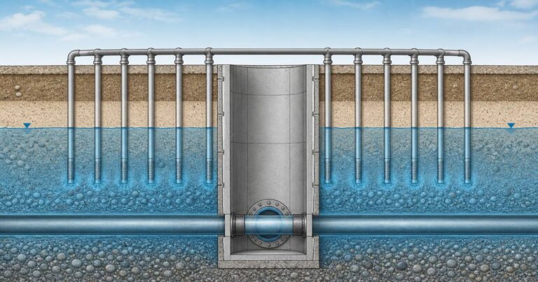
A wellpoint system lowers the water table by suction, and the depth it can reach is limited by atmospheric pressure rather than by pump size. A line of small-diameter risers is jetted into the ground around the shaft and connected to a common header pipe served by a vacuum pump, and atmospheric pressure pushes water up the risers once the pump has pulled a vacuum inside them.
If the question is how deep a shaft can be dewatered before the pump stops being the limit, the answer is set by suction lift rather than by pump size: a single-stage system, as reported in Tunnel Business Magazine, has an effective suction lift of about 4.6 m at sea level, rising to about 6.7 m in particular circumstances, so practical drawdown averages about 5.5 m per stage. Where the required drawdown is deeper, the array is staged, with a second and sometimes a third row set at a lower level. Individual wellpoints typically handle from a fraction of a gallon per minute up to about 100 gpm (US gallons per minute), which is why the spacing of the array and the number of points matter as much as the pump size.
A wellpoint array works best in relatively shallow, stratified, permeable sandy soils, where water moves freely to the points. It cannot be used in ground that contains boulders or cobbles, because the risers cannot be jetted in reliably.
On drives we have supported, the array spacing has mattered more than the pump rating once the drawdown target was fixed.
- Good fit: shallow shafts in layered sands and gravels with a free-draining water table.
- Marginal: silty ground where yield is low and settlement risk is present.
- Not suitable: ground with boulders or cobbles, or any situation where suction lift cannot reach the target level.
- Design inputs: required drawdown, cut-off level, permeability, and an assessment of settlement outside the shaft.
Deep wells, cut-off and the dewatering design sequence
When the aquifer is thick or the drawdown is large, deep wells replace wellpoints. A deep well is a pumped borehole with a screen set against the permeable layer, and the array is sized on the required drawdown and on the cut-off level that the design must achieve. Because each well can be pumped independently, deep well systems reach greater depths and higher yields than suction-based wellpoints.
A cut-off wall is the other half of deep drawdown. A secant pile wall or a grouted curtain can reduce the amount of water that reaches the excavation, which lowers both the pumping rate and the drawdown outside it. Where the surrounding ground is sensitive, cut-off is often the difference between a permissible and an impermissible settlement outside the shaft.
- Define the target drawdown and the cut-off level (the water level to be kept out) for each shaft.
- Estimate inflow from permeability, aquifer thickness and boundary conditions.
- Size the wells or points and the pumps, including standby capacity.
- Predict drawdown and settlement beyond the excavation, and compare with the limits.
- Plan discharge, treatment and consent conditions.
- Install piezometers and a monitoring plan that can detect deviation early.
Ground freezing, grouting and compressed air as water-control options
Where pumping is unacceptable or impractical, groundwater is controlled by changing the ground rather than by removing the water. Ground freezing circulates a chilled brine or liquid nitrogen through a ring of probes until the saturated soil around the shaft or the eye freezes into a strong, watertight block. It is used where dewatering would cause settlement, where contamination or saline groundwater rules out discharge, or where a deep aquifer makes pumping uneconomic.
Grouting is the more common alternative. Cementitious and suspension grouts fill larger voids, while low-viscosity and chemical grouts penetrate finer ground to reduce permeability and bind loosened soil. Jet grouting creates columns of treated ground that can act as a cut-off, and it is often used locally around an entry or exit eye where running ground is expected.
Compressed air is a long-established method for stabilizing a face below the water table, but it is limited by equipment pressure limits and by the physiological restrictions on working in air. It is therefore a specialist choice, best judged for deep shafts with man-entry working rather than for the small, non-man-entry machines that dominate microtunneling. The microtunneling machine class is generally quoted over a diameter range of 150-1000 mm, and the machine type is ground-dependent, so the support method and the machine must be selected together.
Entry and exit seals as a pressure boundary
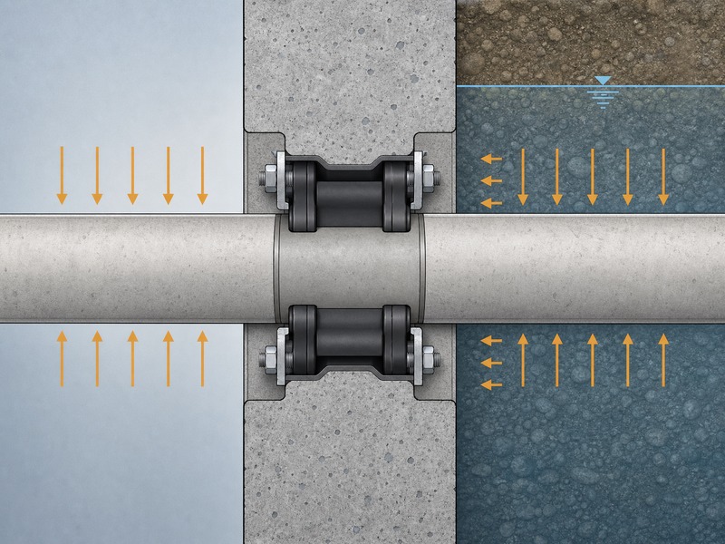
The entry and exit eyes are the points where the drive crosses from the dry shaft into the wet ground, and they are the most pressure-critical detail on the whole alignment. Below the water table, a headwall and seal assembly in both the thrust and reception pits prevents groundwater ingress and ground loss, and also retains annular lubricant. A properly designed seal keeps water and soil out of the shaft as the machine passes.
An entry or exit seal must be designed to withstand hydrostatic and slurry pressures throughout launch, reception and the whole tunnelling operation, including the moment of breakthrough. The design has to tolerate the eccentricity of the machine as it passes through, keep the seal in contact with the pipe, and allow the seal to be replaced or maintained if the drive is long. Where the ground at the eye is loose or running, the seal is usually combined with local ground treatment so that the opening can be broken through safely.
In our design reviews we treat the eye seal as a piece of temporary works rather than a detail, because it is the only barrier at the moment of breakthrough.
Pressure balance in the drive: slurry density and face support
Once the machine is in the ground, microtunneling groundwater control shifts from exclusion at the shafts to balance at the face. A slurry machine provides earth pressure to balance lateral earth loads and slurry pressure to balance groundwater pressure. If the support pressure is too low, the face loses ground and settlement follows; if it is too high, the ground can be lifted or the slurry can escape to the surface along a weak path.
The slurry does two jobs at once: it supports the face and it carries the excavated material back to the surface. Its density and filtration behavior are therefore control variables, not just transport properties. The separation plant must be able to increase slurry density to counter slurry loss and prevent face collapse, and approval is typically required if a separation plant is not proposed at all for a slurry drive.
The face itself is often conditioned before it will hold. Injecting bentonite, water, polymers or foam into the plenum conditions loose sands and gravels so they can form a pressure plug. This is the same logic that governs ground conditioning for earth-pressure-balance machines, which have only limited ability to work below the water table, particularly in non-cohesive soils. Because the groundwater regime can change along the alignment, the pressure set point is reviewed as the drive advances rather than fixed at the start.
When Dewatering Is Not Permissible, and What Replaces It
Whether pumping is allowed is read differently: a municipal drainage owner weighs the ground it must protect, an EPC bidder weighs the discharge consent, and a water utility owner weighs its aquifer. Dewatering is attractive because it is familiar and reversible, but it is not always permissible. Three constraints decide it, and each changes the method: a compressible profile above the water table, contaminated water, and a saline aquifer.
- Soft clays and peats: avoid drawdown; use cut-off, ground freezing or a sealed shaft.
- Contaminated groundwater: minimize volumes; treat and dispose, or use exclusion methods.
- Saline aquifers: control the cone of depression to prevent intrusion.
This is where our field teams record the value of an early decision. Choosing exclusion over pumping after the shaft is designed is expensive; choosing it during the geotechnical stage is cheap. The test compares predicted drawdown settlement outside the shaft with the permitted movement of the nearest asset; if it exceeds that, the method changes. The site investigation should therefore measure permeability and the nature of groundwater flows, including seasonal and tidal changes, and it should install piezometers so that the baseline is known before construction.
Every microtunneling groundwater control figure in this article is an input to project-specific design and must be confirmed by a competent engineer for the actual drive. Depth envelopes, suction limits and pressure set points are planning markers, not design outputs, and they change with the ground, the aquifer and the surroundings.
The shaft geometry that sets how deep the drawdown has to go is treated in our shaft sizing guide, the permeability and groundwater record in our geotechnical investigation guide, and the face support system in our slurry microtunneling guide.
Frequently asked questions
Why is groundwater control critical in microtunneling?
Groundwater controls shaft stability, face support and settlement. Below the water table, water pressure acts on the shaft base, the entry and exit eyes and the tunnel face at the same time, so a single weak point can stop a drive.
What depth can wellpoint dewatering reach?
Wellpoints typically dewater to about 5.5 m per stage. A single-stage system has an effective suction lift of about 4.6 m at sea level and up to about 6.7 m in particular circumstances, so staged systems are used for deeper shafts and drives.
When should deep wells be used instead of wellpoints?
Deep wells are used when the required drawdown or the permeability exceeds what wellpoints can achieve. They are sized on the required drawdown and cut-off level, and they suit thick, permeable aquifers that must be lowered before a shaft is excavated.
How does ground freezing help at a microtunneling shaft?
Ground freezing turns saturated soil into a strong, watertight block. It is used where dewatering would cause settlement or where contamination, saline groundwater or a deep aquifer rules out pumping, and it also stabilizes running ground at the entry and exit eyes.
What pressure should slurry be held at to balance groundwater?
Slurry pressure is set above the local groundwater pressure. The margin must be enough to support the face without lifting the ground, and slurry density is increased to counter loss and prevent face collapse.
When is dewatering the wrong solution?
Dewatering is the wrong answer where drawdown would damage the surroundings. In soft clays, contaminated groundwater or saline aquifers, the settlement, disposal or intrusion risk can outweigh the benefit, so cut-off walls, ground freezing or a sealed shaft are used instead.
Key takeaways
- Groundwater control has to work at three boundaries at once: the shaft, the entry and exit eyes, and the tunnel face.
- A wellpoint system is limited by suction lift of about 4.6 m per stage in normal conditions, averaging about 5.5 m of drawdown, and cannot be used in ground with boulders or cobbles.
- Deep wells, cut-off walls, ground freezing and grouting are the alternatives when the required drawdown, the ground or the surroundings rule out simple pumping.
- The choice is normally exclusion before pumping where the water table is high and the surroundings are sensitive, because drawdown settlement is the hardest effect to reverse.
- Entry and exit seals must be designed for hydrostatic and slurry pressure for the whole operation, not just at breakthrough.
- In the drive, the support pressure must sit above groundwater pressure but below the level that lifts the ground, with slurry density used to counter loss.
- Every microtunneling groundwater control figure here is a planning marker; the actual method and its parameters must be confirmed for the specific drive.
How JSW supports microtunneling groundwater control
JSW is a pipeline engineering and construction company that executes trenchless drives with its own crews and equipment. Our scope covers microtunneling construction, where the water-control method is chosen with the shaft and the pipe, trenchless technologies for crossings that need a different method, servicios de instalación de tuberías y pipeline repair services, and emergency response and contingency maintenance where a live main cannot wait.
We work on an integrated design-and-construct basis, which means the dewatering or exclusion strategy, the shaft design and the drive pressure balance are developed together rather than handed between parties. Our records are built so that they can be audited, and our pricing states the groundwater risk explicitly instead of carrying it as an allowance. Safety, consent compliance and clear reporting on discharge and settlement are treated as part of the engineering, not as administration.
- Integrated delivery: shaft, groundwater control and drive planned by one team.
- Risk-explicit pricing: groundwater uncertainty identified and priced, not hidden.
- Records that can be audited: drawdown, discharge and pressure data reported daily.
- Compliance and safety: disposal and consent conditions managed as design requirements.
Planning a drive below the water table? Send your ground investigation, groundwater data and shaft locations for a free technical review. Our engineers respond with a scoped recommendation, whether exclusion or pumping governs, the depth envelope we would expect to govern and a budget range.





































 English
  Arabic
  Russian
  Spanish
  French
  Vietnamese
  Polish
  Thai
Thai  Indonesian
  Turkish
  Portuguese