
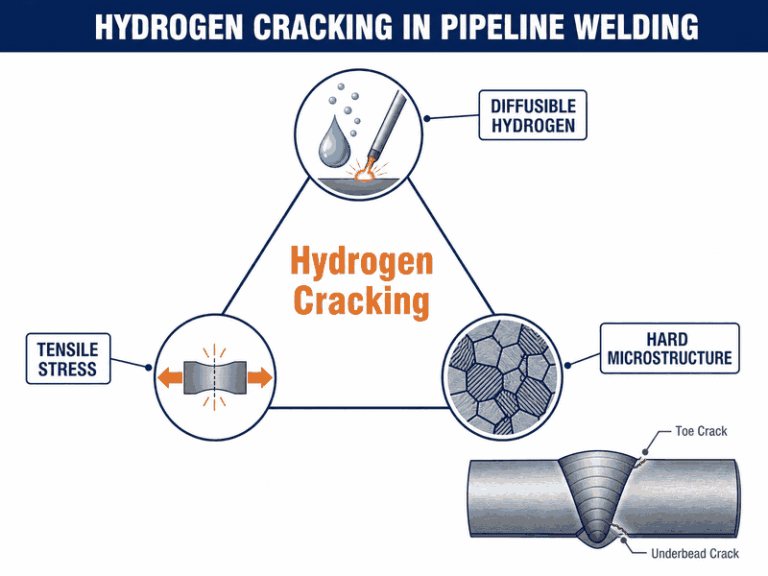
Hydrogen cracking in pipeline welding is the delayed cold cracking failure that occurs when diffusible hydrogen, a hard susceptible microstructure, and tensile stress act together in a finished weld. You prevent it by using low-hydrogen consumables, correct preheat, interpass control, and delayed inspection so hidden cracks cannot reach service.
This guide explains the hydrogen cracking mechanism, the three conditions that must exist for it to occur, seven field-proven prevention measures with typical parameters, the extra rules for sour service and high-strength line pipe, and the inspection timing that catches delayed cracking before it becomes a leak.
Key Takeaways
- Hydrogen cracking needs three conditions at once: diffusible hydrogen, a hard microstructure, and tensile stress. Remove any one and the crack cannot form.
- Moisture is the main hydrogen source: damp electrodes, wet bevels, rust, and humid air. Low-hydrogen consumables with 5 mL/100 g or less diffusible hydrogen are the baseline.
- Preheat to 100-150 °C for most carbon steel girth welds, and higher for thick wall, high CE, or high restraint. Your qualified WPS (Welding Procedure Specification) governs the exact value.
- Keep interpass temperature within the qualified range and apply post-heat at 200-250 °C for 1-2 hours on thick, restrained, or high-strength joints.
- Inspect on a delay: hydrogen cracks usually appear 48 hours to 2 weeks after welding, so hold the weld before final NDT and cap at 22 HRC on sour lines.
- See Table 2 for the full parameter reference.
What Is Hydrogen Cracking in Pipeline Welding?
Hydrogen cracking in pipeline welding appears as a cold crack in the weld metal or the heat-affected zone (HAZ), often hours or days after the weld has cooled. It is also called delayed cracking, cold cracking, or hydrogen-assisted cracking. The cracks are usually longitudinal, run along the weld toe or under the bead, and are invisible until the weld is inspected with magnetic particle or ultrasonic testing.
The failure starts inside the metal. Atomic hydrogen from the welding process dissolves into the molten pool and becomes trapped in the solid weld. At the same time, a fast cooling rate turns the HAZ into a hard, brittle microstructure. When the weld contracts and residual tensile stress builds up, the trapped hydrogen migrates to stress concentrators and drives a crack through the hard zone.
Hydrogen embrittlement of the base metal is a related but separate phenomenon, and it is strongest near room temperature. That is why a weld that looks perfect at the end of a shift can fail two days later, and why hydrogen cracking in welding is treated as a time-delayed defect rather than an immediate one.
What Causes Hydrogen Cracking in Pipeline Welding?
Three conditions must exist together for hydrogen cracking in pipeline welding to occur: a source of diffusible hydrogen, a susceptible microstructure, and tensile stress. This is often drawn as a triangle, and the practical rule is simple: remove any one side and the crack cannot form.
- Hydrogen: moisture in the flux or electrode coating, condensation on a cold bevel, rust, oil, paint, humidity in the shielding gas, or hydrogen absorbed from the product being welded.
- Susceptible microstructure: a hard, martensitic HAZ produced by fast cooling, high carbon equivalent steel, or an excessively high-strength grade.
- Tensile stress: weld metal contraction, joint restraint, thick-wall clamping, or the service pressure applied before hydrogen has diffused out.
| Hydrogen source | How it enters the weld | Primary control |
|---|---|---|
| Damp electrode coating | Moisture in the flux decomposes into hydrogen in the arc | Bake low-hydrogen electrodes per manufacturer; hold at 120-150 °C; limit exposure to 4 hours |
| Wet or contaminated bevel | Condensation, rust, oil, or paint releases hydrogen during welding | Dry and clean 25 mm each side of the joint; preheat to remove condensation |
| Humid environment | Ambient moisture is drawn into the arc and the shielding | Preheat, low-hydrogen consumables, and shorter exposure of opened electrode cans |
| Cellulosic or high-hydrogen consumables | Cellulose coatings contain water that becomes hydrogen in the arc | Use low-hydrogen electrodes or adjust preheat and post-heat in the WPS |
| Product hydrogen (sour gas, hydrogen service) | Hydrogen from H2S or hydrogen gas diffuses into the weld in service | Hardness control, PWHT where required, and NACE-compliant materials |
Carbon equivalent (CE) is the quickest way to judge microstructure risk before welding. The IIW formula is CE = C + Mn/6 + (Cr + Mo + V)/5 + (Ni + Cu)/15. API 5L PSL2 line pipe caps CE at 0.43 for X52 and X60, 0.45 for X65, and 0.48 for X70, and steels near those ceilings need more preheat than low-CE steel.
How to Prevent Hydrogen Cracking: 7 Proven Methods
These seven measures control hydrogen cracking in welding as a system, not as separate options. Each one removes or weakens one side of the hydrogen cracking triangle, and skipping one multiplies the risk of the others. Every method below is used daily in our field work and is written into our qualified procedures.
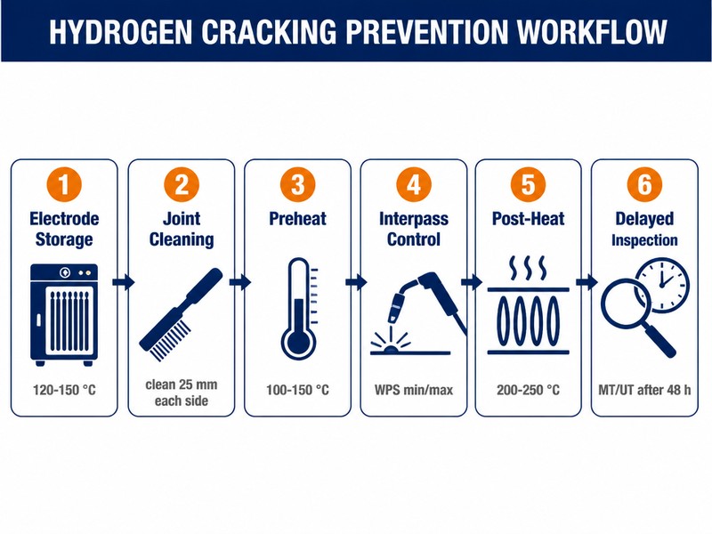
Figure 1. A six-stage field workflow controls hydrogen cracking in welding from electrode storage to delayed inspection.
1. Use Low-Hydrogen Electrodes and Store Them Correctly
Low-hydrogen electrodes such as E7018 are the baseline for pipeline welding where hydrogen cracking is a risk. Their coatings are formulated to keep diffusible hydrogen in the deposit at or below 5 mL/100 g, the H5 classification level measured per ISO 3690 or AWS A4.3.
An electrode is only low-hydrogen if it stays dry. Store low-hydrogen electrodes at 120-150 °C in a rod oven, bake them at the manufacturer’s specified temperature, typically 300-400 °C, before use, and return unused rods to the oven after no more than 4 hours of exposure to air. In our welding department, opened electrode cans are marked with the time they left the oven, and a rod exposed too long is scrapped, not reused.
2. Clean and Dry the Weld Area Before the First Bead
Rust, oil, paint, moisture, and condensation on the bevel are hydrogen sources that no electrode can compensate for. Clean the joint faces and 25 mm on each side of the bevel down to bare metal, and dry the area with preheat where condensation is possible.
On cold mornings, steel surfaces accumulate visible moisture even when the air feels dry. Our site rule is simple: if a weld area shows any sign of dampness, the preheat must stay on until the surface is dry and stays dry, and the temperature is measured with a contact thermometer or infrared gun before each pass. Our crews carry bevel grinders, wire brushes, and acetone on the right-of-way, and the joint is re-checked visually before every root pass.
3. Preheat to the Correct Temperature
Preheat slows the cooling rate so the HAZ transforms into a tougher microstructure instead of hard martensite, and it drives moisture off the joint before welding. The required preheat depends on carbon equivalent, wall thickness, and restraint; typical carbon steel values are 100-150 °C, rising to 150-200 °C for thick, high-CE, or highly restrained joints.
The temperature is read on the parent metal 75 mm from the weld, not on the weld itself, and it must be held through the entire welding sequence. On a recent 36-inch X70 tie-in in a coastal environment, we welded with 150 °C preheat and checked the temperature with an infrared gun before every electrode change, because humidity was driving the risk.
4. Control Interpass Temperature and Heat Input
Interpass temperature keeps the joint above the transformation window between passes, so each subsequent weld metal and HAZ cools at the controlled rate. It also prevents overheating, which widens the HAZ and burns off alloying elements.
The qualified WPS sets both a minimum and a maximum interpass temperature. Stay inside the range: too low re-creates the fast cooling that makes hard microstructure, and too high degrades toughness. Automatic welding systems with real-time parameter logging make this easier to hold than manual welding, which is one reason automatic pipeline welding is increasingly used on large-diameter work.
5. Apply Post-Heat or Hydrogen Bake-Out on High-Risk Joints
Post-heat, sometimes called hydrogen bake-out, holds the completed weld at 200-250 °C for 1-2 hours so trapped hydrogen can diffuse out of the joint while the metal is still above the danger zone for embrittlement. It is applied when preheat alone cannot be maintained, on thick-wall or highly restrained joints, and on high-strength steels.
Hydrogen embrittlement is most severe near room temperature, and steels are largely immune above roughly 150 °C. That makes post-heat a temperature race: the weld is kept hot long enough for hydrogen to escape before the metal ever passes through the cold, brittle window.
6. Use Post-Weld Heat Treatment for Thick-Wall and Sour-Service Lines
Post weld heat treatment (PWHT, also written post-weld heat treatment) at 600-650 °C for carbon steel, typically one hour per 25 mm of wall thickness, softens the HAZ and relieves residual stress. It is the strongest single defense against hydrogen cracking, and it is required by code or owner specification for thick-wall lines, high-strength grades, and sour pipelines where NACE limits apply.
PWHT is rarely applied to long field runs because heating a full pipeline section is impractical; it is used on tie-ins, fittings, and station piping where the joint count is small. When PWHT is not feasible, the combination of low-hydrogen consumables, preheat, and post-heat must carry the hydrogen control burden.
7. Cap Hardness and Inspect on a Delay
Hardness is the measurable proxy for microstructure susceptibility, and a portable survey tells you whether the procedure actually produced the microstructure you planned. In sour service the cap is 22 HRC (~248 HV) per NACE MR0175/ISO 15156-2, and many offshore codes hold non-sour welds near 350 HV.
Because hydrogen cracking is delayed, final NDT must wait. Our standard practice, and common industry practice, is a 48-hour hold before magnetic particle testing (MT) and ultrasonic testing (UT), with longer holds for high-strength steels. A weld that is accepted on the day it is finished can contain a crack that will open up two weeks later.
| Method | Key parameter | When it matters |
|---|---|---|
| Low-hydrogen electrodes | ≤5 mL/100 g (H5); store 120-150 °C; expose <4 h | All carbon steel girth welds |
| Clean & dry joint | 25 mm each side to bare metal | Cold mornings, humid sites |
| Preheat | 100-150 °C (up to 200 °C high CE/thick) | CE > 0.40, thick wall |
| Interpass control | WPS min/max range, logged | Multi-pass, automatic welding |
| Post-heat (bake-out) | 200-250 °C, 1-2 h | Thick, restrained, high-strength |
| PWHT | 600-650 °C, 1 h per 25 mm | Sour service, code requirement |
| Hardness cap + delayed NDT | ≤22 HRC (sour); 48-h hold | H2S lines, X70/X80 |
All seven parameters are fixed by your qualified WPS, and this table is what we hand to site supervisors before every girth weld campaign.
What Preheat Temperature Do You Need?
There is no single universal welding preheat temperature for hydrogen cracking prevention; the value comes from the carbon equivalent, the wall thickness, and the restraint of the joint, and the final number is fixed by your qualified WPS. The table below gives the typical starting ranges we use before qualifying a new procedure.
| Carbon equivalent (CE) | Wall thickness | Typical preheat temperature |
|---|---|---|
| CE up to 0.40 | Up to 25 mm | 50-100 °C |
| CE 0.40-0.45 | 25-50 mm | 100-150 °C |
| CE above 0.45, or high restraint | Over 50 mm | 150-200 °C |
| Sour service (NACE MR0175/ISO 15156-2) | Any | 150 °C minimum in our practice |
Three field rules keep preheat honest. Measure on the parent metal 75 mm from the joint. Maintain the temperature for the full weld, including tack welds, which are welded and kept hot like the root pass. And when ambient temperature is low or the surface is wet, add margin instead of subtracting it.
The ranges in Table 3 are starting points, not substitutes for a PQR; the final value is always confirmed in a PQR (procedure qualification record) before production welding begins.
Hydrogen Cracking in Sour Service Pipelines
Sour service duty raises the stakes because the product itself supplies hydrogen. Hydrogen sulfide in the gas or liquid dissociates at the steel surface, and atomic hydrogen diffuses into the weld in service, which is why hardness control, not just welding hygiene, becomes the governing requirement.
Welding to NACE MR0175/ISO 15156-2 means capping weld and HAZ hardness at 22 HRC, selecting consumables whose undiluted deposit meets the same limit, and frequently applying post-weld heat treatment to low-alloy steels. On sour gas projects the limits below govern the qualified procedure:
- ≤22 HRC (~248 HV) — NACE MR0175/ISO 15156-2 sour service
- ~350 HV max — many offshore codes, non-sour service
- Hardness survey across the weld, HAZ, and parent metal, recorded on the WPS so the inspector sees the proof at the joint
Repairs in sour service carry the same risk. Any weld repair adds a second thermal cycle to an already hardened HAZ, so repairs on sour lines are made with the same preheat, low-hydrogen consumables, and hardness verification as the original weld, and the area is re-surveyed after repair.
Need a sour-service WPS qualified to NACE MR0175? Send us the pipe grade and CE, and our welding engineers will confirm the hardness limits and preheat for your joint.
Hydrogen Cracking Risk in High-Strength Line Pipe
High-strength grades such as X70 and X80 are more sensitive to hydrogen cracking because their strength comes from a microstructure that is easier to over-harden, and their CE limits are near the weldability ceiling. The margin between a sound weld and a hard, cracked HAZ shrinks as the grade goes up.
The controls for high-strength pipe are the same seven measures applied more strictly: lower maximum hydrogen in the consumable, higher preheat, tighter interpass control, and longer NDT delays. Some operators require H4-class electrodes, 4 mL/100 g or less, for X80 and above, and hold final inspection for 72 hours or more.
For hydrogen service pipelines built to ASME B31.12, the same welding controls apply to the weld itself, and hydrogen effects on the base metal in service are a separate design consideration. We treat every high-strength girth weld as a hydrogen-controlled weld until the hardness survey says otherwise.
Qualification welds are made with the same consumables, positions, and ambient conditions as the production joint, so the record matches the field.
How to Inspect for Delayed Hydrogen Cracking
Delayed cracking makes inspection timing part of the prevention system. The crack needs time to grow to a detectable size, so inspecting too early gives a false sense of security, and inspecting too late means the defect is already in the ground.
The standard sequence on our projects is visual inspection immediately after welding, hardness survey where the spec requires it, and magnetic particle or ultrasonic testing after a 48-hour hold. MT catches surface toe cracks and underbead cracks at the surface; UT catches subsurface HAZ cracks that MT cannot see. Radiography is used where the contract demands it, but it is the least sensitive method for tight hydrogen cracks. Automated ultrasonic crawlers log the full scan record, so a re-review after the holding period is a matter of calling up the file rather than re-running the crew.
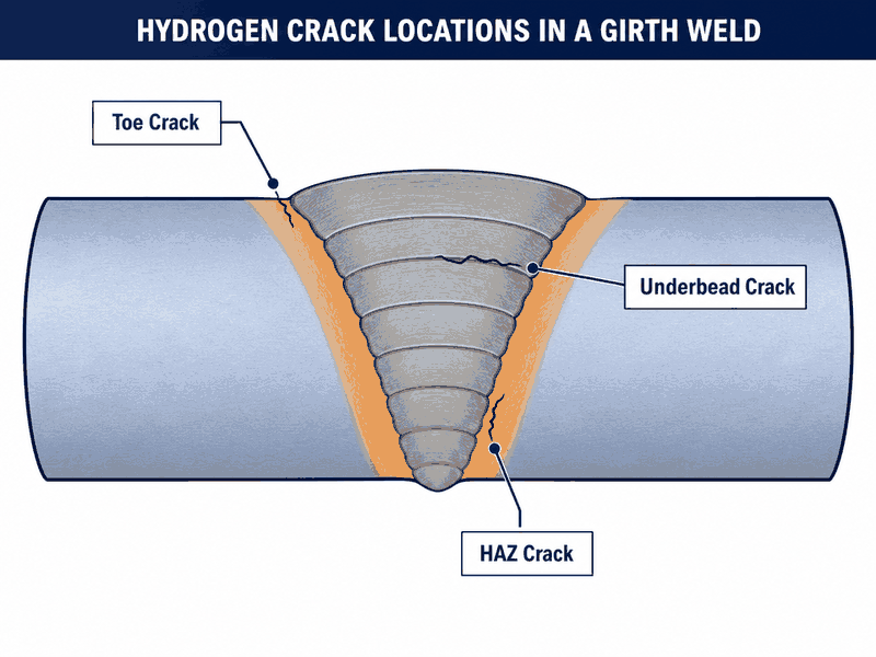
Figure 2. Hydrogen cracks in a girth weld typically form at the weld toe, under the bead, and in the hardened heat-affected zone.
When a hydrogen crack is found, the repair follows the same discipline as the original weld: grind or cut out the full crack with a pipeline cutting machine or grinder, verify removal with MT, re-weld with preheat and low-hydrogen consumables, and re-inspect after another hold. Cutting out only the visible crack leaves the hydrogen-charged zone in place, and the crack returns.
Hydrogen Cracking vs. Hydrogen-Induced Cracking (HIC): What Is the Difference?
Hydrogen cracking and hydrogen induced cracking (HIC) are often confused because the names overlap, but they describe different failure mechanisms. Hydrogen cracking is the cold, delayed crack in a weld caused by hydrogen absorbed during welding. HIC is the blistering and stepwise cracking of the base metal caused by hydrogen absorbed from wet H2S service over years of operation.
Hydrogen cracking in welding forms in hours to weeks, sits in the weld metal or HAZ, and is prevented by welding controls. HIC forms over the life of the pipeline, sits in the parent metal, and is prevented by material selection and hardness limits at the mill. Hydrogen embrittlement is the umbrella term for ductility loss from absorbed hydrogen, and both mechanisms are expressions of it.
In practice, a sour gas pipeline needs defense against both: welding controls to prevent hydrogen cracking in the girth welds, and HIC-resistant line pipe to prevent hydrogen induced cracking in the body of the pipe. Hydrogen induced cracking prevention starts at the steel mill with HIC-tested plate, while hydrogen cracking prevention starts at the weld with electrodes and preheat. Confusing hydrogen cracking with hydrogen induced cracking leads to the wrong prevention program and the wrong inspection schedule.
Frequently Asked Questions
What is hydrogen cracking in pipeline welding?
Hydrogen cracking in pipeline welding is a delayed cold crack in the weld metal or heat-affected zone that forms when diffusible hydrogen, a hard microstructure, and tensile stress are present together. It appears hours to weeks after welding and is usually longitudinal, running along the weld toe or under the bead.
What causes cold cracking in welds?
Cold cracking needs three simultaneous conditions: hydrogen in the weld, a hard susceptible microstructure from fast cooling, and tensile stress. Moisture from damp electrodes or wet bevels supplies the hydrogen, high cooling rate creates the hard HAZ, and weld contraction provides the stress. Remove any one condition and the crack cannot form.
How long after welding does hydrogen cracking occur?
Hydrogen cracks usually appear 48 hours to 2 weeks after welding, which is why the failure is called delayed cracking. The crack needs time for hydrogen to diffuse to a stress concentrator and for the crack to grow to a detectable size, and high-strength steels can crack over longer windows. This is the reason final NDT is held for 48 hours or more.
What preheat temperature prevents hydrogen cracking?
Typical carbon steel preheat is 100-150 °C, rising to 150-200 °C for thick wall, high CE, or highly restrained joints. The exact value comes from your qualified WPS and depends on carbon equivalent, thickness, and restraint. Measure the temperature on the parent metal 75 mm from the weld and hold it for the full weld, including tacks.
Do low-hydrogen electrodes alone prevent hydrogen cracking?
No. Low-hydrogen electrodes are necessary but not sufficient. They must be kept dry, the joint must be clean, and preheat, interpass control, and inspection timing must all be right. An E7018 rod that has absorbed moisture for six hours can deliver more hydrogen than a dry cellulosic rod.
Is post-weld heat treatment required to prevent hydrogen cracking?
Not for every weld. Post-weld heat treatment at 600-650 °C is required for thick-wall, high-strength, or sour-service applications where code limits apply. For ordinary carbon steel girth welds, the combination of low-hydrogen consumables, correct preheat, and post-heat at 200-250 °C is sufficient. Your WPS and the governing code decide.
Hydrogen cracking vs. hydrogen embrittlement: what is the difference?
Hydrogen embrittlement is the general loss of ductility in a metal caused by absorbed atomic hydrogen. Hydrogen cracking is the specific delayed cold crack in a weld caused by hydrogen absorbed during welding. All hydrogen cracking is a form of hydrogen embrittlement, which also includes HIC, blistering, and stress corrosion effects in base metal that no welding control can fix.
Can a hydrogen crack be repaired?
Yes, with the same discipline as the original weld. Grind or cut out the complete crack, verify full removal with magnetic particle testing, re-weld with preheat and low-hydrogen consumables, and re-inspect after another hold. Repairing only the visible crack leaves hydrogen-charged hard material in place and the crack returns, often worse. For field repairs on live pipelines, see our pipeline repair services.
Before you send your inquiry, have these three numbers ready: pipe grade (e.g. X65), wall thickness, and carbon equivalent. Send them to our welding engineers, and we will review the hydrogen cracking risk and confirm the procedure within 24 hours.
Hydrogen cracking in pipeline welding is preventable, but only as a system: dry consumables, clean joints, correct preheat and interpass control, post-heat and post-weld heat treatment where the risk demands it, and inspection on a delay. The three conditions of the hydrogen cracking triangle, hydrogen, hard microstructure, and stress, are all under the welder’s control before the first bead.
Hydrogen cracking prevention is not a code paragraph to look up; it is a field discipline that has to survive cold mornings, humid coastal air, and pressure from the schedule. In our pipeline construction and maintenance work, the joints that fail are almost always the ones where a control was skipped, a damp rod was used, or an inspection was rushed.
If you are planning pipeline construction, repair, hot tapping, or line stopping on carbon steel or high-strength line pipe, work with a team that treats hydrogen control as routine. JSW has completed more than 1,200 hot tap and line stopping jobs, including sour-service tie-in programs, and hundreds of pipeline girth weld programs across Asia, the Middle East, Africa, and South America, with welder and procedure qualifications to API 1104 and ASME B31.4/B31.8. Our pipeline maintenance services and line stopping and plugging equipment cover the repair and maintenance scope for live lines.
Send us your pipe grade, wall thickness, and carbon equivalent — you will get a hydrogen cracking risk review and a quotation within 24 hours.
Get a Free Hydrogen Cracking Risk Review





































 English
  Arabic
  Russian
  Spanish
  French
  Vietnamese
  Polish
  Thai
Thai  Indonesian
  Turkish
  Portuguese