
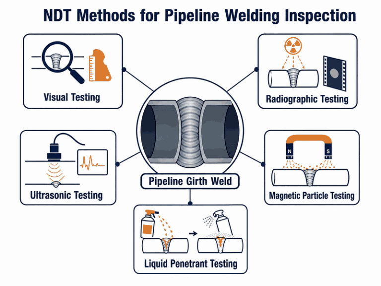
A pipeline welding inspection checklist is a stage-by-stage quality plan that verifies every girth weld against the acceptance criteria of the governing code before final pipeline inspection and commissioning.
It pairs visual examination with non-destructive testing (NDT) methods, specifically radiographic testing (RT), ultrasonic testing (UT), magnetic particle testing (MT), and liquid penetrant testing (PT), to check every weld for internal and surface imperfections.
This guide covers why pipeline welding inspection matters, how each NDT method works, a complete pre-weld, in-process, and post-weld checklist you can apply on site, and how to build a quality assurance program that satisfies API 1104 and ASME B31.8. You will also learn which welding defects each method detects, who is qualified to perform and interpret the tests, and how inspection records are documented for regulators and owners.
What Is Pipeline Welding Inspection?
It is the systematic examination of a weld from joint preparation through final acceptance. It combines visual checks at every stage with non-destructive testing (NDT) of completed welds, and it is always performed against a written acceptance standard, usually API 1104 for cross-country pipelines or the applicable ASME code for facility piping. The inspector does not judge quality by eye alone; every decision is measured against documented limits for size, depth, and distribution of imperfections.
Inspection is not a single event. It happens before the first bead, between passes, after welding, and again after any repair. Each of these checks answers a different question: Is the joint ready? Is the weld being built correctly? Does the finished weld meet the acceptance limits? Skipping any of these stages is how defects survive to the pressure test.
The stakes are measurable. The European Gas Pipeline Incident Data Group (EGIG) recorded 1,463 incidents on the European gas transmission network between 1970 and 2022. Construction defects and material failures caused roughly 18 percent of incidents in the most recent decade, equal to 0.021 of 0.118 incidents per 1,000 km per year. EGIG credits better welding, inspection, and in-line inspection technology for the more than eightfold drop in failure frequency, from 0.86 to 0.10 per 1,000 kilometers per year, and most weld-related failures are preventable at the inspection stage.
Why Quality Assurance Matters in Pipeline Welding
Quality assurance in pipeline welding is the management system that makes inspection effective. It defines the welding procedure specification (WPS), the qualified welders, the NDT extent, the acceptance criteria, and the documentation trail before any work starts. Inspection verifies execution; the QA system verifies the plan. Without the system, inspection results are just data with no owner and no consequence.
A defective weld on a pressurized line can leak, rupture, or propagate a crack over years of service. The consequences include lost product, environmental damage, injuries, and regulatory penalties. The cost of prevention is small by comparison: repairing a weld at the NDT stage costs a fraction of cutting out and re-welding a pipe section after coating, backfill, and reinstatement.
Regulators set the minimum standard. In the United States, 49 CFR Part 192 requires radiography of girth welds on gas transmission lines, with limited exceptions defined in the regulation, and 49 CFR Part 195 applies the same requirement to hazardous liquid lines. Owners typically go further, specifying AUT on large-diameter projects and third-party inspection on high-consequence areas.
JSW’s field records show the same pattern. On a 40-kilometer gas line we audited last year, the repair rate dropped from 11 percent to 2 percent after the contractor introduced a pre-weld joint inspection hold point and began verifying welder qualification against each joint’s position and wall thickness. The welding crews did not change; the inspection system did.
The Core NDT Methods for Pipeline Welding
Five methods dominate pipeline weld examination: visual testing (VT), radiographic testing (RT), ultrasonic testing (UT), magnetic particle testing (MT), and liquid penetrant testing (PT). Advanced forms of UT, including automated ultrasonic testing (AUT) and phased array (PAUT), are specified on large-diameter, offshore, and sour-service lines. Each method detects a different class of imperfection, and no single method finds everything.
Visual Testing (VT)
Visual testing is the first and mandatory NDT step on every pipeline weld. Surface-breaking defects, profile problems, and workmanship errors are visible to the trained eye before any volumetric method is used. Most acceptance codes require a clean weld surface, correct cap profile, and reinforcement within limits before RT or UT is scheduled.
Carry out the examination with calibrated tools: a bridge cam gauge for reinforcement height, a fillet gauge for profile, and a magnifying lamp for fine indications. Check for undercut, surface porosity, spatter, arc strikes, craters, and cap width consistency. Record the result on the weld sheet even when no repair is needed, because the record is part of the QA evidence.
API 1104 requires visual examination of every weld, and ASME Section V governs how the examination is performed. In our projects, visual testing is never delegated to a welder’s self-check alone; a dedicated inspector repeats the pass before volumetric NDT is called.
Radiographic Testing (RT)
Radiographic testing uses X-ray or gamma radiation to image the internal volume of a weld. Porosity, slag inclusions, incomplete fusion, and incomplete penetration appear as density changes on film or a digital detector. RT produces a permanent image that can be reviewed by a second interpreter and retained for the life of the pipeline. Image quality is verified with an image quality indicator (IQI) placed on every exposure, and films are interpreted against the acceptance criteria by Level II or III personnel.
In the field, RT is normally performed with an iridium-192 or selenium-75 gamma source, using the double-wall single-image technique on small-diameter pipe and panoramic exposure on large diameters. Radiation safety requires an exclusion zone, barriers, and dosimetry, which is why RT crews work in shifts and why project schedules reserve time for the exposure sequence.
US regulations require radiography of transmission line welds, and the governing standard defines the acceptance criteria for the resulting images.
Digital radiography is increasingly accepted where the governing specification allows it, because it shortens exposure review from hours to minutes.
Ultrasonic Testing (UT)
Ultrasonic testing sends high-frequency sound pulses through the weld and reads the echoes returned by internal discontinuities. UT is more sensitive than RT to planar defects such as cracks and lack of fusion, and it provides depth and size information that RT cannot.
Manual UT with angle probes is the standard technique for repair welds and for lines where radiography is impractical. It avoids the radiation safety constraints of RT and reports defect depth and size directly on site.
Automated ultrasonic testing (AUT) uses arrays of probes that scan the full weld volume in a single pass and record every indication with position data. Large-diameter projects routinely specify AUT instead of RT because it is faster, requires no radiation exclusion zone, and reports defect position and height, which supports engineering critical assessment. Phased array ultrasonic testing (PAUT) adds electronic beam steering and is widely used for in-service weld assessment.
API 1104 Appendix A covers AUT for mechanized welding, Appendix D provides UT acceptance criteria, and ASME Section V governs the technique and calibration. UT results are only as good as the interpreter, so Level II or Level III certification is mandatory on our projects.
Magnetic Particle Testing (MT)
Magnetic particle testing detects surface and near-surface cracks in ferromagnetic materials. A magnetic field is induced in the weld, and iron particles cluster at any discontinuity that leaks flux, making the indication visible against a contrasting background. MT is the method of choice for toe cracks, crater cracks, and grinding marks that volumetric methods can miss.
Apply MT to root and hot passes of repair welds, to branch connections, and to attachments such as clips and supports. Wet fluorescent MT gives the highest sensitivity for critical welds, while dry powder is common for field work. The surface must be clean and the field direction must be perpendicular to the expected defect orientation, so two field directions are standard practice.
API 1104 and ASME Section V both define MT technique and acceptance rules. We treat MT as mandatory on every weld that has been ground or repaired, because grinding can open a buried crack to the surface.
Liquid Penetrant Testing (PT)
Liquid penetrant testing reveals surface-breaking flaws on any material, which makes it the standard method for austenitic stainless steel and alloy fittings where MT will not work. A dye is drawn into open discontinuities by capillary action, and a developer pulls the dye back out to form a visible indication.
Use color-contrast penetrant in daylight and fluorescent penetrant under UV for higher sensitivity. The surface must be clean, dry, and free of scale, and the method only finds flaws open to the surface; subsurface defects are invisible to PT. It is the right tool for valve bodies, stainless tie-ins, and the final pass of alloy welds, not for volumetric screening of a mainline girth weld.
ASME Section V and API 1104 provide the PT acceptance limits. When a specification calls for PT on stainless steel welds, we record the developer dwell time and temperature on the report, because these variables control sensitivity.
| NDT method | What it detects | Best application | Key limitation | Relative cost |
|---|---|---|---|---|
| Visual testing (VT) | Surface defects, profile, workmanship | Every weld, every stage | Cannot see below the surface | Low |
| Radiographic testing (RT) | Porosity, slag, incomplete fusion and penetration | Regulated girth welds, permanent record | Radiation safety, slower than AUT | Medium to high |
| Ultrasonic testing (UT) | Planar defects, cracks, lack of fusion, sizing | Repair welds, heavy wall, AUT on large diameters | Depends heavily on operator skill | Medium (manual), high (AUT) |
| Magnetic particle testing (MT) | Surface and near-surface cracks | Root and repair welds, attachments | Ferromagnetic materials only | Low |
| Liquid penetrant testing (PT) | Surface-breaking flaws | Stainless and alloy welds | Surface must be clean; no subsurface detection | Low |
How to Choose NDT Methods for Your Pipeline Welds
The governing standard and the project specification decide which NDT methods apply, not the contractor’s preference. API 1104 sets the acceptance criteria for pipeline girth welds, while the design code, such as ASME B31.8 for gas or ASME B31.4 for liquids, and the owner’s specification set the extent of examination. Facility piping under ASME B31.3 follows a different examination schedule based on fluid service category.
Use this rule of thumb: VT on 100 percent of welds, radiography or AUT on the percentage the code and owner require, MT or PT on every ground or repaired area, and additional MT on the root of welds made from one side. The table below maps common project types to their typical NDT programs.
| Project type | Governing code | Typical NDT program |
|---|---|---|
| Onshore gas transmission | ASME B31.8, 49 CFR 192 | VT 100%, RT 100% of girth welds |
| Onshore liquids pipeline | ASME B31.4, 49 CFR 195 | VT 100%, RT 100% |
| Large-diameter or offshore line | ASME B31.8 / DNV or owner spec | VT 100%, AUT or RT 100%, MT on root and repair |
| Facility process piping | ASME B31.3 | VT 100%, RT or UT per fluid service category |
| Hot tap and repair welds | API 1104 in-service rules | VT, MT or PT on fillet welds, RT or UT per spec |
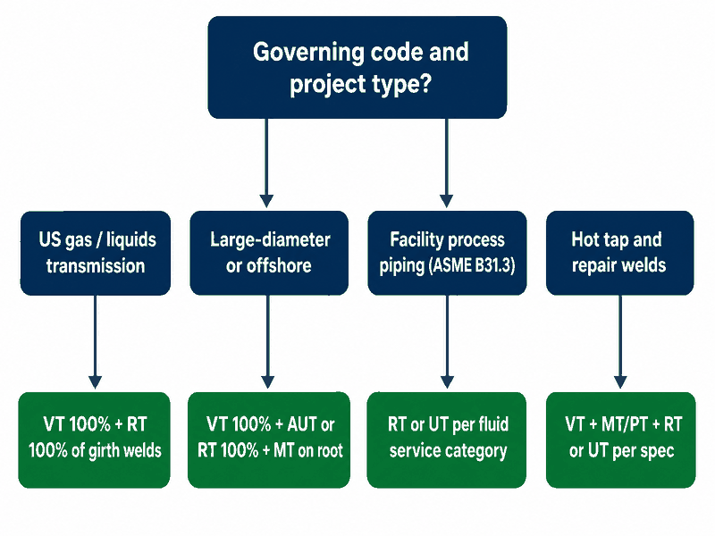
Figure 1. NDT selection starts with the governing code, then adds methods based on weld criticality and material.
The Complete Pipeline Welding Inspection Checklist
Key takeaways:
- Every weld passes through three inspection stages, pre-weld, in-process, and post-weld, each with its own hold points.
- VT is mandatory on 100 percent of welds; RT or AUT covers the code-required percentage.
- MT or PT is required on every ground or repaired area.
- All NDT interpretation requires Level II or Level III certification.
Use this checklist as a field reference. It is organized into three stages, before welding, during welding, and after welding, because most weld failures are set up before the first bead or during the root pass, not at the final NDT stage. Every check below is a hold point: the next operation does not start until the check is signed off.
Pre-Weld Inspection Checklist
- Welding procedure specification (WPS) and procedure qualification record (PQR) are available and match the joint in process, position, material, and thickness range.
- Welder qualification is valid for the process and position of this joint; the welder’s stamp or card number is recorded against the weld number.
- Bevel geometry, bevel angle, root face, and root gap are within the WPS range, measured with a profile gauge.
- Internal misalignment is within the code limit, typically 1.6 mm on thinner walls and capped at 10 percent of wall thickness on heavy-wall pipe.
- Surfaces within 25 mm of the bevel are free of moisture, rust, mill scale, oil, and paint.
- Preheat temperature is applied and verified with a contact pyrometer or temperature crayon where the WPS requires it.
- Line-up clamps, welding machines, and cables are in working condition; ground connection is secure and away from the weld zone.
- Low-hydrogen electrodes are stored and handled per the manufacturer’s requirements; no damp rods enter the oven or the quiver.
- Environmental controls are in place: wind screens, rain protection, and acceptable ambient conditions for the process.
In-Process Inspection Checklist
- Root pass is fully fused at the root, free of cracks, and internal reinforcement is within the acceptance limits.
- Interpass temperature stays within the WPS band; cooling below minimum or exceeding maximum is a stop-work condition.
- Slag and spatter are removed between passes; no arc strikes or stray arcs outside the weld groove.
- Welding parameters, current, voltage, and travel speed, match the WPS and are spot-checked during the shift.
- Back purge gas flow is verified for stainless steel and critical alloy welds; purge is maintained until the root pass is complete.
- Bead sequence and weave width follow the WPS; weaving beyond the limit is a common cause of lack of fusion.
- The hot pass follows the root pass without delay where the WPS or code requires it, to avoid root cracking.
Post-Weld Inspection Checklist
- Final visual inspection covers cap profile, reinforcement height, undercut, surface porosity, and cap width.
- Reinforcement height does not exceed 1.6 mm on walls below 12.7 mm and 2.4 mm on thicker walls, per API 1104.
- Undercut depth does not exceed 0.8 mm, and any undercut beyond this limit is repaired before NDT.
- Weld identification, stencil number, and weld map location are recorded before NDT scheduling.
- NDT is performed per the specification: RT or UT extent, MT or PT on repairs, and all interpretations by certified personnel.
- NDT reports, radiographic images or digital files, UT charts, and MT/PT sheets are signed, dated, and filed with the weld record.
- The completed package includes the weld log, NDT summary, qualification evidence, and material traceability records.
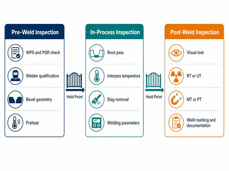
Figure 2. The three-stage inspection workflow runs through pre-weld, in-process, and post-weld checks, each with its own hold points before work can continue.
| Stage | Critical check | Acceptance basis | Responsible |
|---|---|---|---|
| Pre-weld | WPS and welder qualification match the joint | API 1104 Chapters 4 and 6, or ASME Section IX | QA engineer |
| Pre-weld | Joint geometry, cleanliness, preheat | WPS range and code limits | Welding inspector |
| In-process | Root pass quality, interpass temperature, purge | WPS and API 1104 | Welding inspector |
| Post-weld | Profile, reinforcement, undercut | Code visual criteria | Welding inspector |
| Post-weld | RT or AUT extent and interpretation | Code and owner specification | NDT Level II/III |
| Post-weld | MT or PT on repairs and attachments | Code / ASME Section V | NDT Level II |
| Documentation | Weld log, NDT reports, traceability | Owner specification and regulator | QA engineer |
Putting this checklist into practice on a live project? Our engineering team can review your WPS, confirm the NDT extent your code requires, and define the hold points for your inspection and test plan. Ask for our printable checklist and inspection and test plan template.
Common Welding Defects and How NDT Catches Them
Knowing which defect each NDT method finds is the difference between an inspection program and a paperwork exercise. The table below lists the welding defects that account for most pipeline weld rejections, the method that detects each one, and the prevention step that stops it from recurring.
| Weld defect | Description | Detected by | Typical cause |
|---|---|---|---|
| Porosity | Gas pockets trapped in the weld metal | RT, UT | Contaminated surface, damp electrodes, lost shielding |
| Slag inclusion | Flux or slag trapped between passes | RT, UT | Incomplete slag removal between passes |
| Incomplete fusion | Weld metal fails to fuse with the base metal or previous pass | UT, RT | Low heat input, wrong travel speed, excessive weave |
| Incomplete penetration | Root of the joint is not fully filled | RT, UT | Root gap too small, root face too large, low root current |
| Undercut | Groove melted into the base metal beside the weld toe | VT | Excessive current, wrong electrode angle |
| Crater crack | Crack at the end of a weld bead | VT, MT, PT | Broken arc without filling the crater |
| Toe or hydrogen crack | Crack at the weld toe or in the heat-affected zone | MT, UT | Hydrogen, restraint, missed preheat |
| Arc strike | Stray arc damage outside the weld groove | VT, MT | Poor grounding, careless technique |
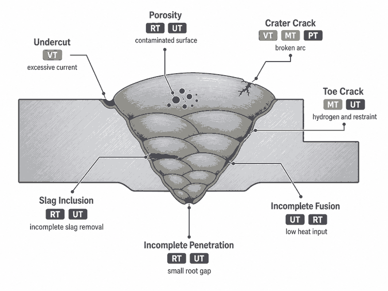
Figure 3. Each welding defect has a primary detection method, which is why a quality program combines volumetric and surface NDT.
In practice, the reject mix tells you where the process is failing. Porosity and slag inclusions usually point to consumables and cleaning discipline. Incomplete fusion and penetration point to parameters and technique. Cracks point to preheat, restraint, and hydrogen control. When we see the same defect repeat on three consecutive welds, we stop the line, review the WPS against the actual conditions, and requalify before restarting.
Who Should Perform Pipeline Welding Inspection?
Pipeline weld inspection is performed by certified inspectors and NDT technicians, not by welders checking their own work. Visual inspectors typically hold an AWS Certified Welding Inspector (CWI) or CSWIP Welding Inspector certification. NDT personnel are qualified to ASNT SNT-TC-1A, ISO 9712, or the national scheme in force on the project, and interpretations of RT and UT are made at Level II or above.
Welder qualification is a separate requirement that the inspection team verifies before each joint. API 1104 Chapter 6 defines the qualification tests for pipeline welders, and ASME Section IX covers welders on facility piping. A qualification earned under one system is not automatically valid under the other, so the inspector checks the card against the exact process, position, and thickness range of the job.
| Certification | Scope | Issuing body | Typical requirement |
|---|---|---|---|
| AWS CWI | Welding inspection and acceptance | American Welding Society | Written exam, code book open, periodic renewal |
| CSWIP Welding Inspector | Welding inspection and acceptance | TWI Certification | Written and practical exam, 3-year renewal |
| ASNT SNT-TC-1A Level II | NDT method execution and interpretation | Employer-certified per written practice | Training hours, practical exam, visual acuity |
| ISO 9712 / PCN Level II | NDT method execution and interpretation | Certification body | Training, exam, recertification every 5 years |
On our projects we require documented certification for every signature on an NDT report, and we maintain a register of current cards with expiry dates. A report signed by someone whose certification lapsed is not just a quality problem; it is a legal exposure for the operator.
How to Build a Pipeline Welding Quality Assurance Program
A pipeline welding QA program turns the checklist into a repeatable system. Start with an inspection and test plan (ITP) that lists every weld-related activity, the inspection method, the acceptance limits, and the hold point where work stops for verification. Issue it to the contractor before mobilization and treat it as a contract document.
Document control is the second pillar. The WPS and PQR must be the qualified revisions, qualification cards must be current, and NDT procedures must match the method specified. Every revision is tracked, and superseded documents are removed from the site copy. We have seen a single outdated WPS revision cause an entire day of welds to be cut out.
Data and traceability complete the system. Each weld number links to the welder, the WPS, the NDT results, and the material heat number. Weld maps show the location of every joint and every repair. NDT summary sheets reconcile the number of welds made against the number examined, so an inspector cannot quietly skip a percentage. Records are retained for the life of the pipeline or as the owner and regulator require.
Third-party inspection adds independence. Where the owner or the code requires it, an external inspection organization witnesses the hold points and audits the documentation. Independent surveillance does not replace the contractor’s inspectors; it verifies that the quality assurance program is actually running on site. JSW provides third-party inspection and QA documentation support on API 1104 and ASME B31.3/B31.4/B31.8 projects across oil, gas, water, and chemical sectors.
Common Pipeline Welding Inspection Mistakes
- Inspecting only after welding is complete, which misses root and interpass defects that must be caught live.
- Accepting a weld on a verbal “it looks fine” instead of measuring against the documented acceptance criteria.
- Failing to verify welder qualification against the exact process, position, and thickness range of the joint.
- Reducing NDT extent to save cost without owner approval, which voids the QA record.
- Using uncalibrated gauges and temperature devices, which makes every recorded value questionable.
- Missing environmental control, such as welding in wind or rain without screens, which causes porosity and hydrogen pickup.
- Leaving documentation to the end of the job, so weld numbers, NDT reports, and traceability records no longer match.
Each of these mistakes is a failure of the QA system, not of the welders. When a project is behind schedule, the first pressure point is inspection. Our advice to owners is consistent: protect the hold points, because the cost of a skipped check is paid at the hydrostatic testing stage, where a missed defect becomes a leak, a re-test, and a cut-out in the ditch.
Frequently Asked Questions
What is the difference between NDT and destructive testing in pipeline welding?
Non destructive testing (NDT) examines a weld without damaging it, so the weld remains in service after the test. Destructive testing, used in procedure and welder qualification, cuts, bends, or breaks test coupons to prove the weld’s mechanical properties. Production welds are examined with NDT; destructive testing is reserved for qualification.
Which NDT method is best for pipeline welds?
There is no single best method. Radiographic testing (RT) provides a permanent record and is required by US regulations for regulated lines, while AUT is faster, safer, and better at sizing planar defects on large-diameter projects. The right combination is VT on all welds, RT or AUT per the code and owner specification, and MT or PT on repairs and attachments.
How much NDT is required on pipeline welds?
The governing code and the owner’s specification set the extent. US gas and liquids transmission regulations require radiography of girth welds, and many operators specify 100 percent RT or AUT on critical lines. Facility piping under ASME B31.3 bases examination extent on fluid service category. The inspection and test plan states the percentage for each weld class.
Who can perform pipeline welding inspection?
Visual inspection is performed by certified welding inspectors such as AWS CWI or CSWIP holders. NDT methods are executed and interpreted by personnel certified to ASNT SNT-TC-1A, ISO 9712, or the applicable national scheme, normally at Level II or above. All certifications must be current and documented in the project quality records.
What happens when a weld fails NDT?
The failed area is marked, recorded on the weld map, and repaired by a qualified welder following a documented repair procedure. The repair is re-examined with the same method that found the defect, plus MT or PT on the ground area. Every repair is logged, and a repeat failure rate above the project threshold triggers a process review, not just another repair.
Is AUT better than RT for pipeline weld examination?
AUT and RT answer different needs. AUT is faster, eliminates radiation exposure, and provides defect position and height data that support fracture assessment, which is why large-diameter and offshore projects prefer it. RT provides a permanent image that many regulators and owners still require. The choice belongs in the project specification, based on code, diameter, and acceptance philosophy.
What does a pipeline welding inspection checklist include?
The checklist covers three stages of checks. The pre-weld stage verifies the WPS, welder qualification, joint preparation, and preheat; the in-process stage checks the root pass, interpass temperature, and cleaning between passes; the post-weld stage checks cap profile, reinforcement, undercut, NDT extent, and documentation. Every check is a hold point tied to a written acceptance standard. The completed record links each weld number to the welder, the procedure, the NDT results, and the material traceability files.
How much does pipeline welding inspection cost?
Inspection cost is driven by four variables: the NDT methods required, the number of welds, access and line size, and the certification level of the personnel. RT and AUT are the most expensive methods per weld, while VT, MT, and PT are relatively low cost. The governing code fixes the required extent, so the main cost lever is the weld count and the repair rate, which is why a strong pre-weld inspection program pays for itself.
What are the acceptable limits for pipeline weld imperfections?
API 1104 defines the acceptance criteria for pipeline girth welds. Reinforcement height is limited to 1.6 mm on walls below 12.7 mm and 2.4 mm on heavier walls, and undercut depth is limited to 0.8 mm. Volumetric imperfections such as porosity and slag inclusions are assessed against the code’s size and distribution tables, and cracks of any size are rejectable. The acceptance limits in the inspection and test plan must match the qualified revision of the code.
A pipeline welding inspection checklist is the operating core of any QA program: verify the joint before welding, verify the weld while it is being made, verify the finished weld with the right NDT methods, and document every result against a written acceptance standard. The data is clear: disciplined welding and inspection practices cut European gas pipeline failure frequencies by more than eightfold over five decades, and most weld-related failures are preventable at the inspection stage. The system works when the hold points are protected and the records are honest, because a defect caught by NDT costs minutes while the same defect found at hydrostatic testing costs days of rework.
If you are preparing a welding inspection plan for a new transmission line, a repair weld program on an operating pipeline, or a complete QA package for a station tie-in, send our engineering team at JSW your pipe size, wall thickness, fluid, operating pressure, and governing code. We will confirm the compliant NDT approach and provide a quotation, and we can supply the inspection and welding equipment plus certified personnel to execute the work.





































 English
  Arabic
  Russian
  Spanish
  French
  Vietnamese
  Polish
  Thai
Thai  Indonesian
  Turkish
  Portuguese