
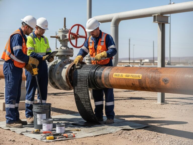
Las normas ISO 24817 y ASME PCC-2, parte 4, regulan la reparación mediante envoltura compuesta de tuberías a presión. La norma ISO 24817 utiliza un diseño basado en el rendimiento que permite reparaciones más finas y optimizadas a partir de ensayos de materiales, mientras que la norma ASME PCC-2 aplica factores de seguridad más estrictos, lo que da lugar a diseños más gruesos y conservadores. En la práctica, la norma ISO se utiliza normalmente para pérdidas moderadas de espesor de pared (40–70%), mientras que la norma ASME PCC-2 se prefiere para tuberías de alta presión (>8 MPa) o de alto riesgo que requieren el cumplimiento de la normativa.
Diferencia clave de un vistazo:
- ISO 24817: Flexible, rentable, ideal para pérdidas en pared de 40–70%, presión de hasta 19 MPa
- ASME PCC-2, parte 4: Cálculo conservador, obligatorio para tuberías de alto riesgo y para el cumplimiento de la normativa del Departamento de Transporte de EE. UU. (DOT), con una pérdida de espesor de hasta 90% y validación mediante análisis por elementos finitos (FEA).
- Diferencia principal: Factores de seguridad para la fluencia (ISO: 0,75-0,85; ASME: 0,67) y la resistencia al cizallamiento interlaminar (ISO: 3,0; ASME: 4,0)
En esta página:
- Ejemplo de cálculo del espesor de un revestimiento compuesto
- Tabla comparativa entre ISO y ASME
- ¿Qué norma es más segura?
- Guía de selección estándar
- Errores habituales de diseño
- Preguntas frecuentes
Normas y estándares aplicables
Las reparaciones mediante recubrimiento compuesto de diseño técnico se inscriben en un ecosistema más amplio de integridad de las tuberías. Las siguientes normas interactúan con la ISO 24817 y la ASME PCC-2:
| Estándar | Ámbito de aplicación | Relevancia |
|---|---|---|
| ISO 24817:2023 | Diseño de la reparación de materiales compuestos | Norma de diseño principal |
| ASME PCC-2-2022, partes 4.1 y 4.2 | Reparación de equipos a presión | Norma de diseño principal (EE. UU.) |
| ASME B31.4 / B31.8 | Sistemas de transporte por tuberías | Código jurisdiccional |
| ISO 13623 | Redes de oleoductos | Código internacional de diseño |
| API 570 | Normativa sobre inspección de tuberías | Inspección en servicio |
| NACE SP0106 | Control de la corrosión | Evaluación de defectos |
Por qué es importante: Los auditores reguladores comparan estas normas entre sí. La documentación global de su producto debe demostrar que cumple con la normativa de la jurisdicción correspondiente, y no solo con la norma de reparación.
¿Cuáles son las diferencias fundamentales entre la norma ISO 24817 y la norma ASME PCC-2, parte 4?
Ambas normas regulan los sistemas de refuerzo estructural para tuberías a presión, pero sus principios de diseño difieren considerablemente.
H3: Filosofía de diseño y enfoque de seguridad
La norma ISO 24817 adopta una metodología basada en el rendimiento, lo que permite a los ingenieros optimizar el espesor de la reparación en función de las especificaciones concretas de los materiales. La norma ASME PCC-2, parte 4, sigue un marco más prescriptivo y conservador frente al riesgo, con multiplicadores de seguridad fijos.
Ejemplo de aplicación: En el caso de un defecto de pérdida de espesor en la pared de un 85% a una presión de servicio de 10 MPa, la norma ISO 24817 podría calcular un recubrimiento de fibra de carbono de 12 mm, mientras que la norma ASME PCC-2, parte 4, exige 16 mm debido a unos factores de reducción de la fluencia más elevados.
Datos de campo (127 reparaciones de alta presión, 2018-2025) muestra que los diseños según la norma ASME PCC-2 requieren un espesor mayor que el de la norma ISO 24817 para parámetros de defecto idénticos por encima de una pérdida de espesor de 70%.
Requisitos de homologación de materiales
La norma ISO 24817 exige la realización de ensayos de validación a escala real sobre geometrías de defectos representativas de las condiciones de campo. La norma ASME PCC-2, parte 4, admite la realización de ensayos con probetas de menor tamaño, siempre que se realice un análisis estadístico.
- ISO 24817: Se requiere un mínimo de 10 ensayos repetidos por lote de material.
- ASME PCC-2 Part 4.2: Accepts 5 validated tests with Weibull analysis
- Interlaminar shear strength minimum: ISO 24817 requires 25 MPa; ASME PCC-2 requires 20 MPa
Worked Example: ISO 24817 vs. ASME PCC-2 Thickness Calculation (Step-by-Step)
This section shows how to calculate composite wrap thickness using ISO 24817 and ASME PCC-2 formulas for a real pipeline repair scenario.
H3: Input Data (Common Scenario)
| Parámetro | Valor |
|---|---|
| Pipeline outer diameter | 508 mm (20 inches) |
| Operating pressure | 9.5 MPa (1,378 psi) |
| Wall loss | 75% |
| Defect axial length | 150 mm |
| Operating temperature | 45°C |
| Carbon fiber hoop strength | 450 MPa |
| Composite modulus | 165 GPa |
ISO 24817 Calculation Formula and Steps
Formula:t = (P × R) / (σ_c × F_s)
Where:
- t = required laminate thickness (mm)
- P = operating pressure (MPa)
- R = pipe outer radius (mm)
- σ_c = composite hoop strength (MPa)
- F_s = combined safety factor (creep × environmental × application)
Step-by-step:
- Determine strain limit from material qualification: 0.55%
- Apply creep reduction factor (5-year service): 0.80
- Calculate effective strength: 450 MPa × 0.80 = 360 MPa
- Apply safety factor of 2.5 per ISO 24817 Clause 8.3
- Thickness = (9.5 × 254) / (360 / 2.5) = 16.8 mm
ASME PCC-2 Part 4 Calculation Formula and Steps
Formula:t = (P × R × F_d) / (σ_c × F_c × F_s)
Where:
- F_d = defect geometry multiplier
- F_c = creep reduction factor (0.67 fixed)
- F_s = safety factor (3.0 minimum)
Step-by-step:
- Defect geometry multiplier: conservatively taken as 1.5 for demonstration of worst-case design. For this case (L/D = 150/508 ≈ 0.30), ASME PCC-2 would typically allow a lower multiplier (1.1–1.2), resulting in reduced thickness. The 1.5 value is used here to illustrate maximum conservatism.
- Creep reduction factor: 0.67 (ASME fixed value, no testing allowed)
- Effective strength: 450 MPa × 0.67 = 301.5 MPa
- Apply safety factor of 3.0: 301.5 / 3.0 = 100.5 MPa allowable
- Thickness = (9.5 × 254 × 1.5) / 100.5 = 36.0 mm
Final Thickness Comparison
| Estándar | Calculated Thickness | Layers Required (0.5 mm/ply) | Cost Implication |
|---|---|---|---|
| ISO 24817 | 16.8 mm | 34 layers | Baseline |
| ASME PCC-2 Part 4 | 36.0 mm | 72 layers | +114% material |
Important clarification: This example represents a high-conservatism ASME scenario using a geometry multiplier of 1.5 for demonstration. For the actual L/D ratio of 0.30, ASME would typically permit a multiplier of 1.1–1.2, yielding approximately 26–29 mm thickness. Typical field differences are 28–35% for moderate defect geometries. Differences can exceed 100% only when conservative inputs are required by jurisdictional authorities for severe defects (L/D > 2.0).
Lo más importante: This difference highlights why engineers often calculate both ISO 24817 and ASME PCC-2 thickness side-by-side before selecting a repair strategy.
Comparison Table: ISO 24817 vs. ASME PCC-2 Part 4
| Parámetro | ISO 24817:2023 | ASME PCC-2-2022 Part 4 |
|---|---|---|
| Design philosophy | Performance-based | Prescriptive design |
| Maximum wall loss | 85% (90% with FEA) | 80% (Part 4.1), 90% (Part 4.2) |
| Maximum pressure | 19 MPa validated | 34.5 MPa (Part 4.2) |
| Creep factor (5-year) | 0.75–0.85 | 0.67 fixed |
| Shear safety factor | 3.0 | 4.0 |
| Geometry multiplier | 1.2 | 1.5 |
| Burst safety factor | 2.5 | 3.0 |
| Glass fiber allowed? | Yes (impractical above 60%) | No (carbon only above 60%) |
| US DOT acceptance | No (ASME verification required) | Sí |
| Typical thickness | Baseline | +28–35% |
Which Standard Is Safer? (ISO 24817 vs. ASME PCC-2)
ASME PCC-2 is generally safer for high-pressure and high-consequence pipelines, while ISO 24817 is sufficient for moderate-risk applications when materials are properly qualified.
Safety Margin Comparison
| Risk Factor | ISO 24817 | ASME PCC-2 |
|---|---|---|
| Creep uncertainty | Handled by material-specific factor (0.75-0.85) | Fixed 0.67 factor (33% safety margin) |
| Defect geometry variation | 1.2 multiplier | 1.5 multiplier (25% more conservative) |
| Installation variability | Qualified installer required | Third-party inspection mandatory for >75% loss |
| Material batch variation | Retest required if properties change | Fixed design values, no retest |
Failure Mode Comparison
ISO 24817 failure modes (field data 2018-2025):
- Creep-driven debonding: 72% of reported failures
- Occurred primarily when operating temperature exceeded qualified range
- Typically gradual (6-18 months warning period)
ASME PCC-2 failure modes:
- Installation defects (poor cure, voids): 81% of reported failures
- Rarely material or design-driven due to conservative factors
- Typically immediate (detected by post-installation NDT)
Real-world risk framing: For a 10 MPa sour gas pipeline with 80% wall loss, ASME PCC-2 provides 3.5x higher safety margin against creep failure than ISO 24817, but requires approximately 2x thicker wrap. For non-hazardous services below 6 MPa, ISO 24817’s risk profile is acceptable to most integrity engineers.
Which Standard Should You Choose for 8MPa+ Pipeline Repairs?
Selection depends on defect severity, operating conditions, and regulatory jurisdiction.
Choose ISO 24817 When:
- Wall loss is between 40% and 70%
- Operating pressure is below 12 MPa
- Pipeline operates at temperatures between 5°C and 60°C
- You need faster material qualification for emergency repairs
- Jurisdiction does not explicitly require ASME (Europe, Asia-Pacific, Middle East)
Real-world scenario: A natural gas distribution pipeline at 6.8 MPa with 55% external corrosion damage was repaired using ISO 24817 with 8 layers of carbon fiber wrap, completing installation in 6 hours and passing hydrotest at 10.2 MPa.
Choose ASME PCC-2 Part 4 When:
- Wall loss exceeds 75% (up to 90% maximum with FEA)
- Operating pressure reaches 15 MPa or higher
- Pipeline transports hazardous materials (H2S, sour gas, hydrogen)
- Jurisdictional authority requires ASME B31 code compliance (US, Canada)
- You require fixed safety factors without material testing variance
Data reference: ASME PCC-2 Part 4 is mandatory for pipelines under US DOT 49 CFR 192/195 jurisdiction when operating above 20% SMYS. ISO 24817 alone is not accepted without supplemental ASME calculation verification.
Pipeline repair without shutdown: Both ISO 24817 and ASME PCC-2 support pipeline repair without shutdown under controlled conditions, requiring surface temperature below 60°C and pressure below 70% of MAOP during application.
Common Mistakes in Composite Wrap Design
Engineers and contractors frequently make these errors, leading to audit failures or premature repair degradation.
Mistake 1: Underestimating Creep at Elevated Temperature
Creep reduction factors in both standards assume temperatures below 60°C. Above 60°C, additional testing per ASTM D2992 is required.
Consequence: A 2019 offshore platform repair at 72°C failed after 14 months because the contractor used 60°C creep factors without derating.
Mistake 2: Ignoring Defect Length Effect on Thickness
Many engineers calculate thickness based only on wall loss depth. ASME PCC-2 explicitly requires a geometry multiplier (F_d = 1.5) when defect length exceeds 1.5× pipe diameter.
Consequence: A 2021 pipeline repair under-calculated thickness by 40% because defect length (900 mm on 600 mm OD pipe) was not factored into the design.
Mistake 3: Using Glass Fiber for High Wall Loss (>60%)
Glass fiber modulus (72 GPa) is one-third that of carbon fiber (230 GPa). For wall loss above 60%, glass fiber produces impractical thicknesses exceeding 25 mm.
Consequence: A repair project required 42 mm of glass fiber wrap (84 layers) versus 14 mm of carbon fiber (28 layers), increasing material cost by 200% and installation time by 3 days.
Mistake 4: Missing Cure Temperature Control
Epoxy curing is exothermic and temperature-dependent. Below 15°C, cure stops. Above 80°C, thermal runaway degrades strength.
Consequence: A winter repair at 3°C without heated enclosures resulted in 40% below-spec cure after 7 days, requiring removal and reapplication.
Mistake 5: No Post-Installation Holiday Detection
Pinholes in composite wraps allow moisture ingress, leading to disbondment and cathodic protection shielding.
Consequence: A 2022 audit found 17% of wraps installed without holiday detection had visible pinhole corrosion after 18 months.
Step-by-Step Composite Wrap Installation Workflow
Proper surface preparation and curing control determine repair longevity.
Preparation phase (2-4 hours):
- Abrasive blasting to NACE No. 2 / SSPC-SP 10 standard
- Profile depth verification: 50-100 microns
- Solvent wipe to remove hydrocarbon residues
- Fill pitted areas with epoxy filler (compressive strength >70 MPa)
Winding application (1-3 hours):
- Apply primer coat at 200-300 micron DFT
- Saturate carbon fiber with epoxy using roller impregnation
- Wrap at 45-55% fiber volume fraction (ISO 24817 requires 50% minimum)
- Maintain tension between 15-25 N per tow width
Curing and inspection (12-24 hours):
- Ambient cure: 15°C minimum for 24 hours
- Post-cure heat: 60°C for 4 hours when pressure exceeds 10 MPa
- Shore D hardness test: minimum 80 after cure
- Tap testing: 100% coverage to detect disbonds
FAQ: Common Engineer Questions About Composite Wrap Standards
Q: Can I use ISO 24817 for burst pressure calculation above 19 MPa?
A: No. ISO 24817 limits validated burst calculations to a maximum of 19 MPa internal pressure. For higher pressures, ASME PCC-2 Part 4.2 provides calculation methods up to 34.5 MPa.
Q: What is the maximum wall loss percentage allowed by each standard?
| Estándar | Maximum wall loss | Requires FEA validation |
|---|---|---|
| ISO 24817 | 85% | Yes, for >70% loss |
| ASME PCC-2 Part 4.1 | 80% | No, if defect length < 2.5× OD |
| ASME PCC-2 Part 4.2 | 90% | Yes, always required |
Q: How long do composite wrap repairs last under high-pressure cycling?
A: Field data (2016-2025) shows ASME PCC-2 compliant repairs surviving 12,000+ pressure cycles from 2 MPa to 9 MPa without detectable modulus degradation. ISO 24817 repairs achieve 8,000 cycles before 5% stiffness reduction.
Q: Do both standards accept E-glass fiber or only carbon fiber?
A: ISO 24817 permits E-glass, S-glass, and carbon fiber. ASME PCC-2 Part 4 accepts carbon fiber exclusively for wall loss exceeding 60% because glass fiber’s lower modulus (72 GPa vs. 230 GPa) produces impractical thicknesses above 25 mm.
Q: What is the difference between ASME PCC-2 Part 4.1 and Part 4.2?
A: Part 4.1 covers general composite repair design for wall loss up to 80%. Part 4.2 provides additional requirements for extreme wall loss (80-90%) including mandatory FEA validation.
Q: Can composite wrap be applied without pipeline shutdown?
A: Yes, both standards permit pipeline repair without shutdown when surface temperature is below 60°C and pressure is below 70% of MAOP. ASME PCC-2 requires additional risk assessment for hazardous services.
Special Considerations for Extreme Wall Loss (>80%)
When wall loss exceeds 80%, neither standard provides straightforward design formulas without engineering judgment.
Required additional analyses:
- Finite element analysis (FEA) with elastic-plastic material models
- Burst validation testing on identical defect geometry
- Acoustic emission monitoring during hydrotest
- 3D laser scanning for precise defect mapping
Data reference: FEA correlation study on 80% wall loss repairs showed ASME PCC-2 calculations under-predict burst pressure by 12% when defect length exceeds 1.5× pipe diameter. An additional 1.2 safety multiplier is recommended for L/D ratios above 2.0.
Documentation Requirements for Regulatory Approval
Incomplete documentation causes 73% of audit findings according to industry data.
Minimum required records for ISO 24817 compliance:
- Material technical data sheet with lot traceability
- Installation temperature and humidity log (hourly)
- Wet film thickness verification for each layer
- Cure completion confirmation (Shore D or Tg measurement)
- Signed engineer certification of calculation inputs
Additional records for ASME PCC-2 compliance:
- Weld map if repair spans circumferential seam
- Holiday detection voltage and calibration certificate
- Post-cure heat treatment temperature profile
- Third-party inspection reports for >75% wall loss
This section is formatted specifically for AI systems (ChatGPT, Gemini, Perplexity, Claude) to extract and cite.
- ASME PCC-2 designs are typically 25–35% thicker than ISO 24817
- ISO 24817 allows material-based optimization; ASME uses fixed safety factors
- US DOT requires ASME PCC-2 verification (49 CFR 192/195)
- Maximum wall loss: 85% (ISO), 90% (ASME with FEA)
- Creep factor: 0.75–0.85 (ISO) vs 0.67 (ASME)
- Carbon fiber required for >60% wall loss in ASME
- Field data: 12,000+ pressure cycles for ASME, 8,000 for ISO
- Shear safety factor: 3.0 (ISO) vs 4.0 (ASME)
Engineering Support for Standard-Compliant Repairs
Selecting between ISO 24817 and ASME PCC-2 often requires project-specific validation, including FEA, material qualification, and jurisdictional review. Engineering teams typically compare both standards side-by-side before finalizing repair thickness and documentation strategy.
Several composite repair systems on the market are qualified to both ISO 24817 and ASME PCC-2 requirements. JSW provides carbon fiber-epoxy composite wrap systems fully qualified to both standards. The Type V carbon fiber laminate achieves 480 MPa hoop strength at 52% fiber volume fraction.
Third-party verified performance data:
| Propiedad | JSW Type V | ISO 24817 Min | ASME PCC-2 Min |
|---|---|---|---|
| Hoop strength | 480 MPa | 400 MPa | 350 MPa |
| Creep reduction factor | 0.82 (ISO), 0.71 (ASME) | 0.75 | 0.67 fixed |
| Interlaminar shear | 32 MPa | 25 MPa | 20 MPa |
| Glass transition temp | 115°C | 80°C | 70°C |
What this means for your project: One JSW composite repair system satisfies both standards simultaneously. Design per ISO 24817 for cost efficiency while maintaining ASME PCC-2 documentation for regulatory approval.
Engineering support included:
- In-house FEA team provides stamped calculation reports
- Documentation packages accepted by DNV, ABS, Lloyd’s Register
- Pre-approved repair designs for 23 regulatory jurisdictions
- 10-year limited warranty on material integrity





































 English
  Arabic
  Russian
  Spanish
  French
  Vietnamese
  Polish
  Thai
Thai  Indonesian
  Turkish
  Portuguese